
Resistance System for a Rowing Machine

Inactive Publication Date: 2020-06-25
NU SPORT CO LTD
View PDF29 Cites 7 Cited by
  • Summary
  • Abstract
  • Description
  • Claims
  • Application Information

AI Technical Summary

Benefits of technology

The resistance system of the rowing machine has a simple structure, making it easy to assemble and reducing manufacturing costs. It also has a longer service life, improving the machine's durability.

Problems solved by technology

However, a structure of the magnetic brake is complex and needs high manufacturing cost.
Moreover, after being stretched repeatedly, elastic fatigue occurs in the elastic rope.

Method used


Image

  • Resistance System for a Rowing Machine
  • Resistance System for a Rowing Machine
  • Resistance System for a Rowing Machine

Examples


Embodiment Construction

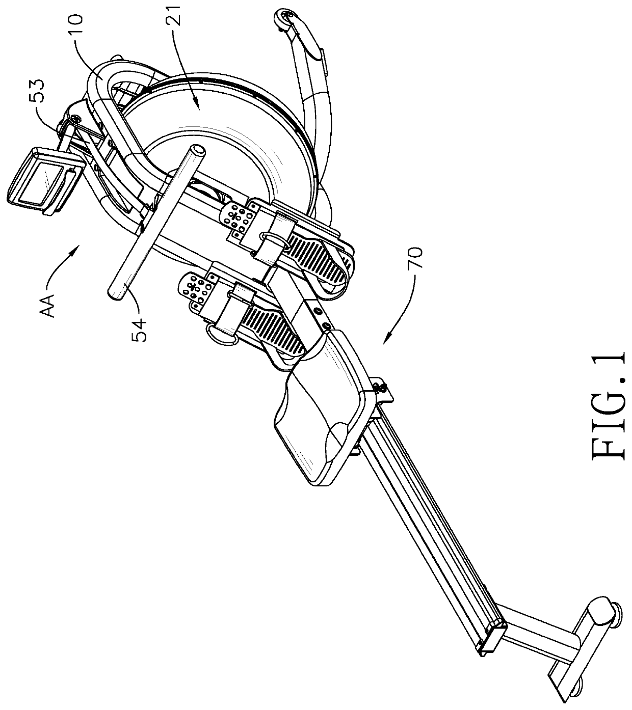
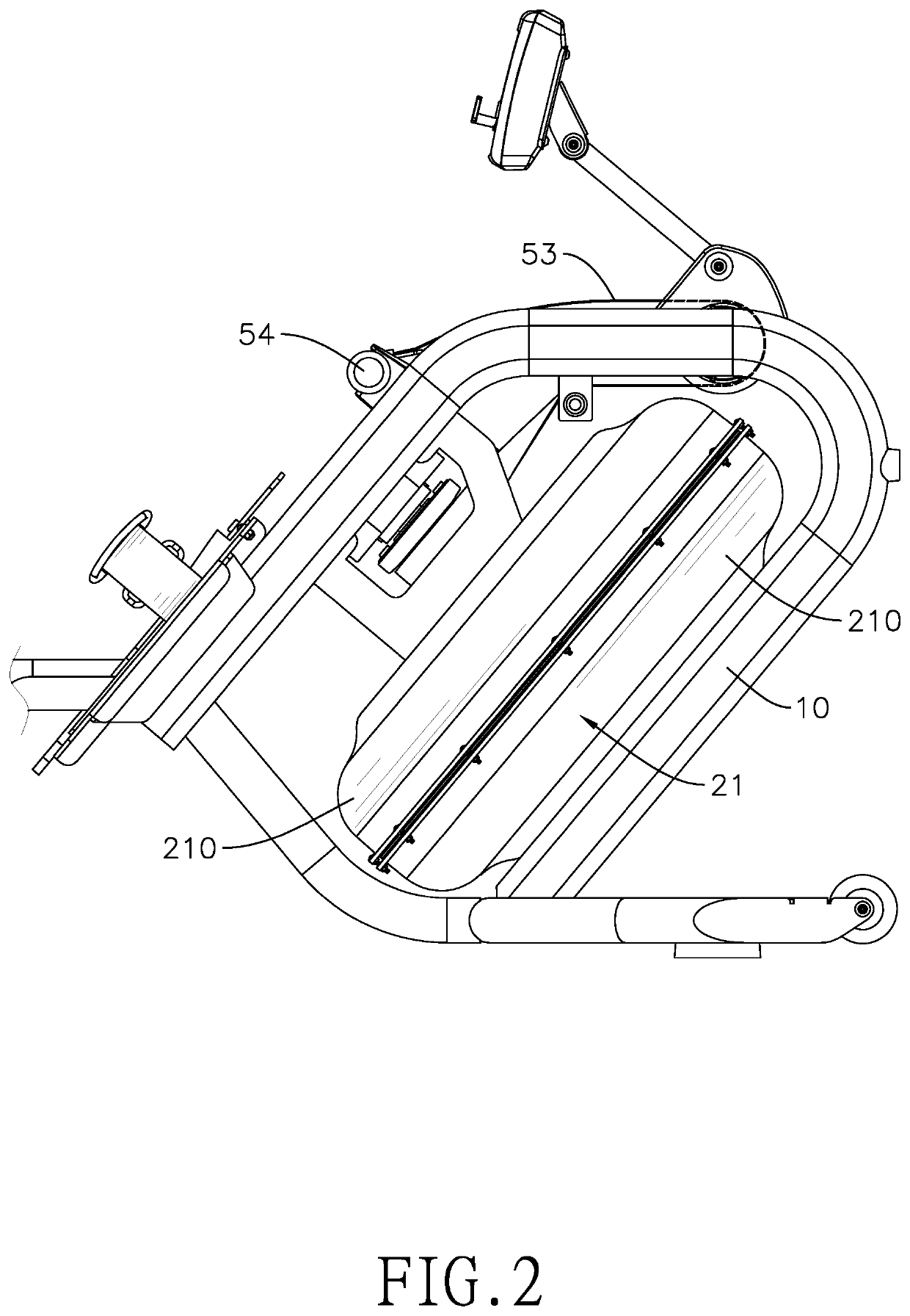
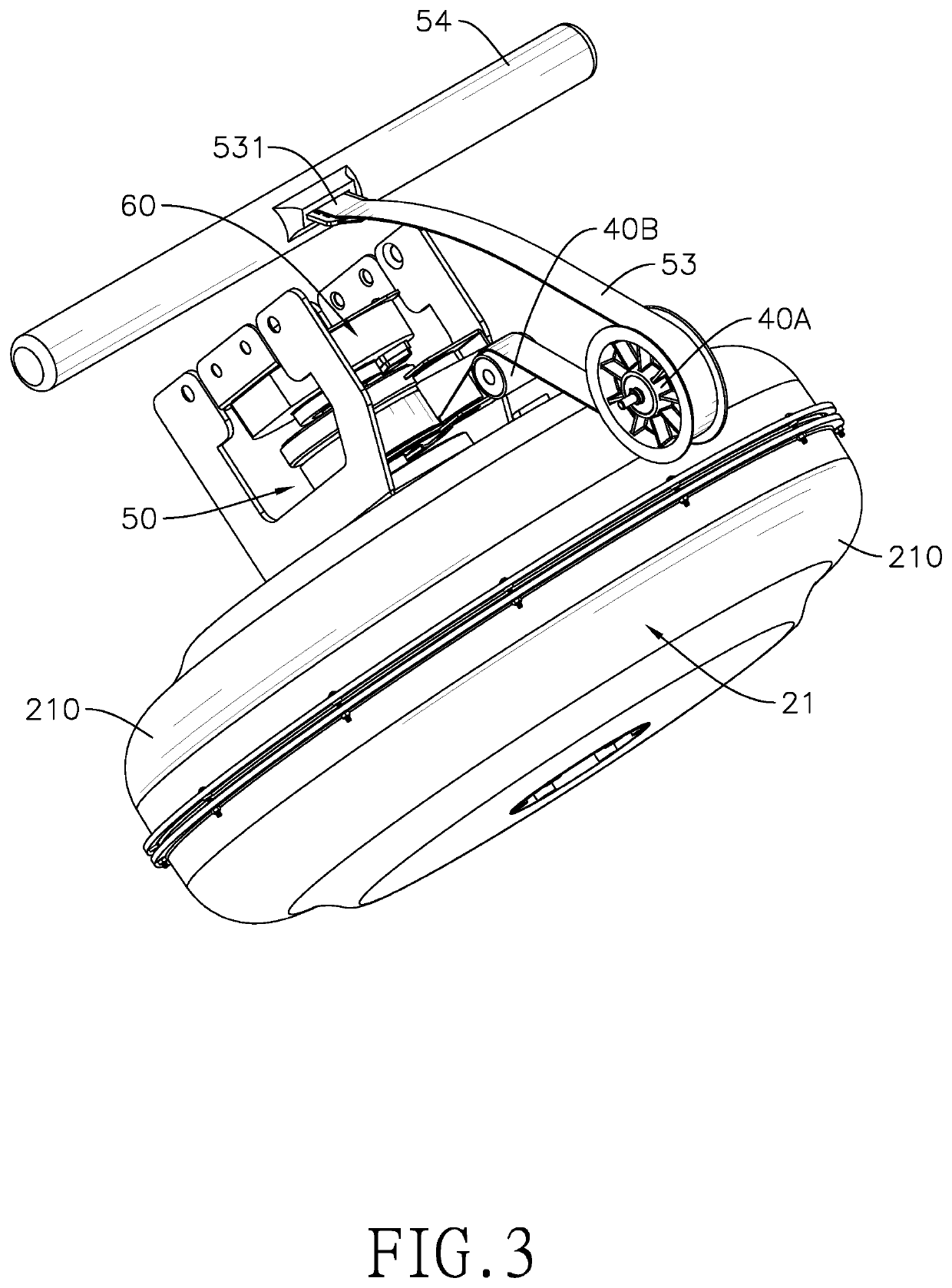
[0021]With reference to FIGS. 1 to 3, a resistance system AA for a rowing machine comprises a mounting bracket 10, a housing assembly 20, a paddle wheel 30, at least one strip guiding member 40A, 40B, a driving assembly 50, and a restoring assembly 60.

[0022]The mounting bracket 10 is connected to a front end of a seat assembly 70 of the rowing machine.

[0023]With further reference to FIGS. 2 and 5, the housing assembly 20 is mounted on the mounted bracket 10 and includes a liquid tank 21 and two baffles 22.

[0024]The liquid tank 21 is for storing liquid such as water, and has two side walls 211 and an annular wall 212. The side walls 211 are oppositely defined on the liquid tank 21. The annular wall 212 is formed between the two side walls 211.

[0025]The baffles 22 are disposed in the liquid tank 21 and are attached to the two side walls 211 of the liquid tank 21 respectively. Each of the baffles 22 is annular and has a through hole 221 defined through the baffle 22. An interior of the...


PUM


Abstract

A resistance system for a rowing machine has a mounting bracket, and a housing assembly, a driving assembly and a restoring assembly mounted on the mounting bracket. The housing assembly is for storing liquid and a paddle wheel. The driving assembly is connected to the paddle wheel and drives the paddle wheel to rotate in a direction only. The restoring assembly is connected to a strip hub of the driving assembly and is able to drive the strip hub to rotate in a reverse direction. The resistance system for the rowing machine has simplified structure. Therefore, it is easy to assemble to resistance system, and manufacturing cost of the resistance system can be decreased. In addition, a service life of the resistance system as well as the rowing machine can be increased.

Description

BACKGROUND OF THE INVENTION1. Field of the Invention[0001]The present invention relates to an exercise equipment, especially to a resistance system for a rowing machine.2. Description of the Prior Art(s)[0002]Rowing is an interesting and challenging sport that exercises all the major muscle groups, including quadriceps femoris, biceps, triceps, latissimus dorsi, gluteal, and abdominal muscles. A rowing machine is an exercise equipment that is used to simulate action of the rowing for the purpose of exercise and training the muscles groups.[0003]A conventional resistance system for a rowing machine includes a magnetic brake and an elastic rope. The elastic rope is connected to the magnetic brake and is able to resume its original shape after being stretched. An exerciser pulls the elastic rope repeatedly and resists resistance forces formed by the magnetic brake and elasticity of the elastic rope, so as to achieve exercise and training effects.[0004]However, a structure of the magnet...

Claims


Application Information

Patent Timeline
IPC IPC(8): A63B21/008A63B69/06A63B21/22A63B22/00A63B21/00
CPCA63B2022/0079A63B2069/062A63B22/0076A63B21/0084A63B21/225A63B21/4035A63B69/06A63B21/025
Inventor HSIEH, HSIAO-CHIEH
Owner NU SPORT CO LTD
Learn More