Side-release buckle

Active Publication Date: 2020-07-02
YKK CORP
View PDF0 Cites 2 Cited by
  • Summary
  • Abstract
  • Description
  • Claims
  • Application Information

AI Technical Summary

Benefits of technology

The present invention is a side-release buckle that prevents damage to the buckle's leg portions when a tensile force is applied from belts on both sides in a direction in which the plug and the socket are separated from each other. This is achieved by designing the engaging surface and surface to be engaged with a mountain-like shape to create a space between them to reduce bending stress on the leg, which reduces the likelihood of breaking and increases the reliability of the buckle.

Problems solved by technology

However, the technique disclosed in Japanese Patent Publication No. 2010-022807 can prevent the breakage of the protrusion of the leg portion, that is, the engaging portion, but is not very useful for preventing the other portion of the leg portion, particularly the leg portion from being broken.
However, the effect of preventing the leg portion from being broken is low when a tensile force is applied from belts on both sides in a direction in which the plug and the socket are separated from each other.
When such a tensile force is repeatedly applied or a strong tensile force is applied, a crack may be formed in the leg portion, and the leg portion may be finally broken.
The conventional side-release buckle has not been sufficiently studied to prevent the leg portion from breaking in such a case, and there is still room for improvement.
Further, it has been found that when a force is applied in the direction of bending forward, bending stress is applied to the leg portions of the plug, which causes the leg portions to break.

Method used


Image

  • Side-release buckle
  • Side-release buckle
  • Side-release buckle

Examples


first embodiment

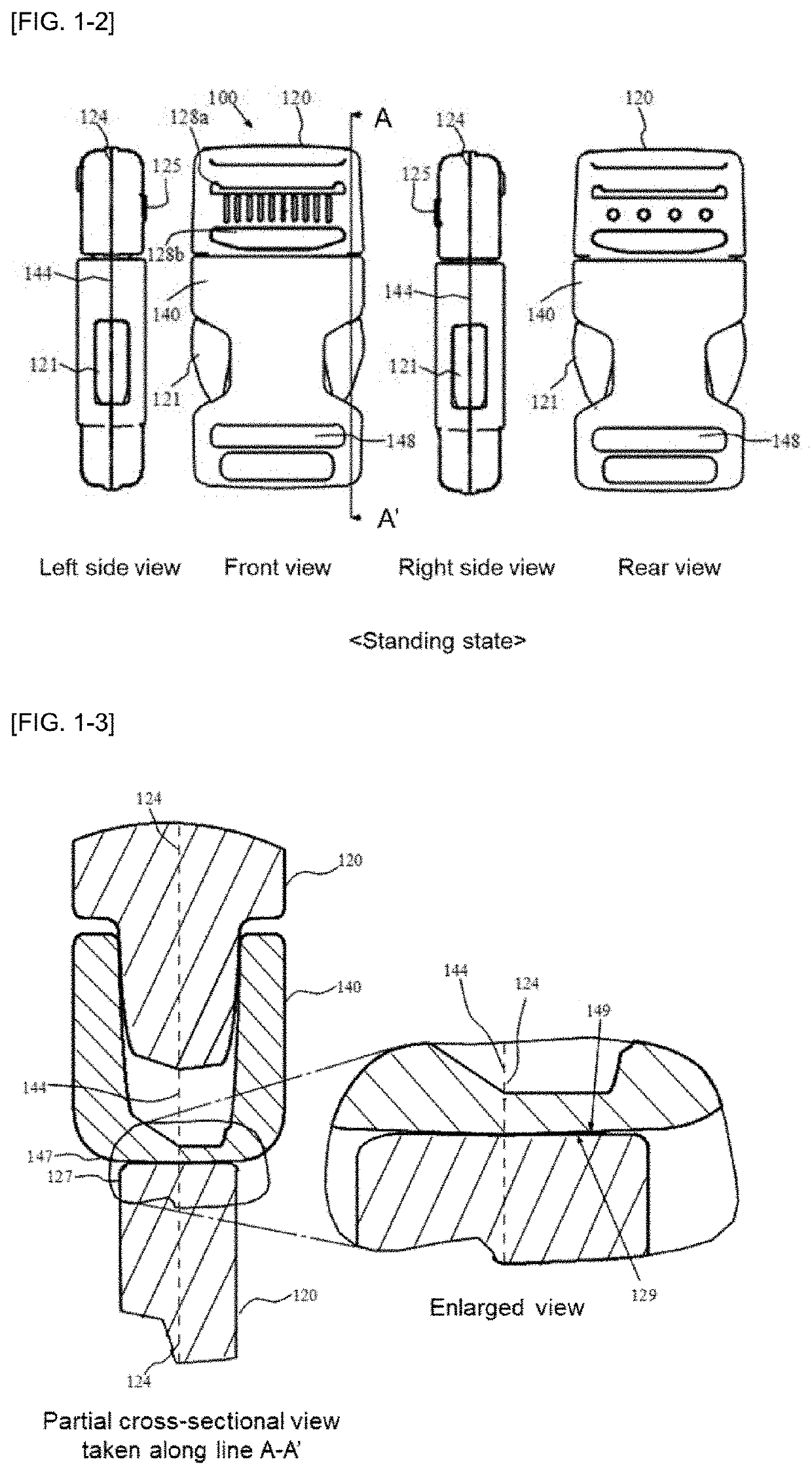
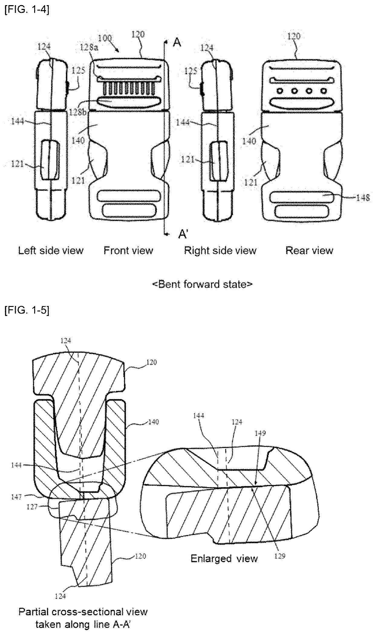
[0051]FIG. 1-1(a) is a perspective view of the side-release buckle (100) according to the first embodiment of the present invention when the plug (120) and the socket (140) are in a separated state. FIG. 1-1(b) is a partial enlarged view of the vicinity of the area surrounded by the circle in (a). FIG. 1-2 is a front view, a rear view, a right side view, and a left side view of the side-release buckle (100) wherein the plug (120) and the socket (140) are in a locked state and both parting lines are in a parallel state. FIG. 1-3 is an enlarged cross-sectional view of the vicinity of the engaging portion (127)of the plug (120) and the portion to be engaged (147) of the socket (140), taken along the line A-A′ of FIG. 1-2. FIG. 1-4 is a front view, a rear view, a right side view, and a left side view of the side-release buckle (100), wherein the plug (120) and the socket (140) are in a locked state and the plug (120) is in a bent forward state. FIG. 1-5 is an enlarged cross-sectional vi...

second embodiment

[0070]FIG. 2-1 is a front view, a rear view, a right side view, and a left side view of the side-release buckle (200) according to a second embodiment of the present invention wherein the plug (120) and the socket (140) are in a locked state. FIG. 2-2 is an enlarged cross-sectional view of the vicinity of the engaging portion (127) of the plug (120) and the portion to be engaged (147) of the socket (140), taken along the line B-B′ of the side-release buckle (200) in FIG. 2-1. Further, FIG. 2-3 is a schematic cross-sectional view of the engaging surface (129) and the surface to be engaged (149) of the side-release buckle (200), in which the plug (120) and the socket (140) are locked, observed from a direction that is an in-plane direction of the first mold mating surface defined by the first parting line (124) of the plug (120), and is also a direction perpendicular to an insertion direction. In FIG. 2-1, FIG. 2-2, and FIG. 2-3, when the same reference numerals as FIG. 1-1, FIG. 1-2,...


PUM


Abstract

According to one of various aspects of the present invention, a side-release buckle includes a plug and a socket for inserting and engaging the plug, and when a cross section of the engaging surface is observed from an in-plane direction of the first mold mating surface defined by a first parting line of the plug, and from an direction perpendicular to an insertion direction, a surface to be engaged is located on the opposite side to a first belt winding portion with respect to the first mold mating surface, and has a first engaging surface forming an angle A1 with the first mold mating surface of 87° or more and 90° or less.

Description

TECHNICAL FIELD[0001]The present invention relates to a side-release buckle used for connecting belts and having a pair of leg portions (lock arms) on both sides.BACKGROUND ART[0002]Conventionally, in addition to belts, in order to connect ends of belts attached to various articles such as bags, rucksacks, clothes, shoes, helmets, sporting goods, and wrappers, buckles for detachably engaging a plug and a socket are used. In such buckles, it is required that the operation for attaching and detaching be easy, and at the same time that buckles should not come off accidentally when not intended. As a product meeting such a demand, a side-release buckle having a pair of leg portions on both sides is known.[0003]Generally, a side-release buckle includes a plug and a socket each having a belt mounting portion. The plug comprises a base portion having a belt mounting portion, and a pair of left and right leg portions (lock arms) protruding from the base portion. An engaging portion is forme...

Claims


Application Information

Patent Timeline
IPC IPC(8): A44B11/25
CPCA44B11/25A44C5/2066A44B11/266
Inventor YOSHIE, KENICHI
Owner YKK CORP
Why Eureka
Try Eureka