
Display panel and display device

Active Publication Date: 2020-07-02
WUHAN CHINA STAR OPTOELECTRONICS SEMICON DISPLAY TECH CO LTD
View PDF0 Cites 2 Cited by
  • Summary
  • Abstract
  • Description
  • Claims
  • Application Information

AI Technical Summary

Benefits of technology

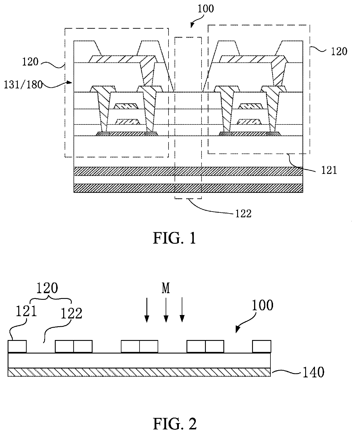
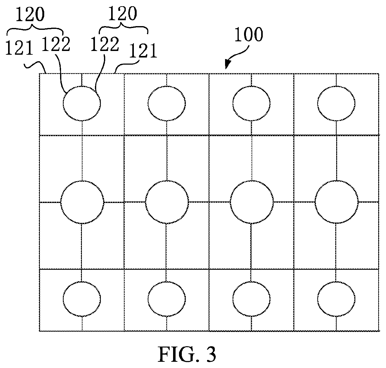
The present invention provides a display panel and display device that improve the quality of images on the screen and increase the screen ratio of the display panel to the display device. The design allows for the photosensitive element, such as a camera, to be integrated with the display screen without needing to reserve space on the display panel, maximizing the screen ratio and improving the user experience. The image display region occupies most of the area of the display panel, and an opening is formed at edge of the image display region, and the light transmissive region is formed within the opening, improving the area of the light transmissive region, the light transmittance, and the image quality. The invention also limits the reduction in pixel density while improving the light transmittance of the light transmissive region.

Problems solved by technology

Therefore, how to integrate camera with display panel to maximize screen ratio is an urgent problem that needs to be solved.
Therefore, display panels need to be sized to accommodate the front camera and a part of the whole device cannot normally be operated, and finally most mobile phones are only be shaped and cut to reduce screen ratio, which is not good to achieve full screen display devices.

Method used


Image

  • Display panel and display device
  • Display panel and display device
  • Display panel and display device

Examples


Embodiment Construction

[0023]It is understood that the terminology, the specific structural details, and the details of the present invention are used for the purpose of describing the specific embodiments and are representative, but the present invention can be embodied in many alternative forms and should not be construed as merely limited by the embodiments set forth herein.

[0024]In the description of the present invention, the terms “first” and “second” are used for descriptive purposes only, and are not to be understood as indicating relative importance or implicitly indicating the number of technical features. Thus, unless otherwise indicated, a feature defining “first” or “second” may include one or more of the features either explicitly or implicitly, and “multiple” means two or more. The term “include” and its conjugations are intended to be inclusive, and may include or add one or more other features, integers, steps, operations, units, components, and / or combinations thereof.

[0025]In addition, ...


PUM


Abstract

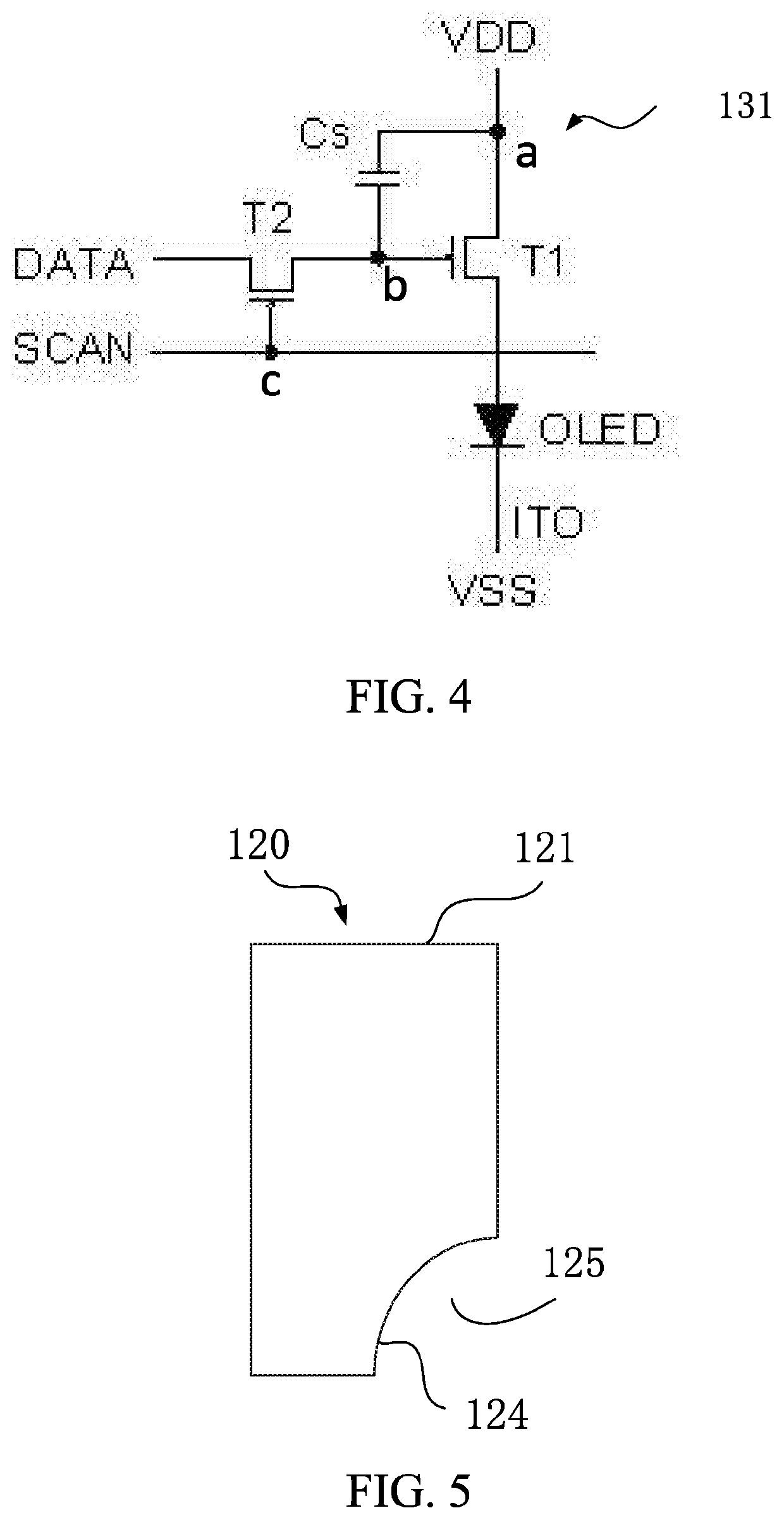
A display panel and a display device are provided. The display panel includes a first driving circuit and a plurality of first pixel units. The first pixel units include an image display region and a light transmissive region, and the image display region is driven by the first driving circuit to provide a corresponding brightness. An opening is formed at an edge of the image display region, the light transmissive region is formed within the opening, and an incident light emitted from an outer side of the display panel passes through the light transmissive region. The image quality of the under-screen camera is improved in term of the pixel density.

Description

BACKGROUND OF INVENTIONField of Invention[0001]The present invention relates to the field of display technology, and more particularly, to a display panel and a display device.Description of Prior Art[0002]With continuous development of the mobile phone industry, mobile phone display panels has also continuously developed, and functions on display panels have also increased. Current mobile phone display panels have been widely provided with camera module. Since camera device needs to be spaced from display panel, an area available for disposing display panel is reduced, which is contrary to the current trend of increasing ratio of mobile phone display panels. Camera module is an essential component of current mobile phones. Therefore, how to integrate camera with display panel to maximize screen ratio is an urgent problem that needs to be solved.[0003]Front camera of display panels is disposed on the outside of display panels. Therefore, display panels need to be sized to accommodat...

Claims


Application Information

Patent Timeline
IPC IPC(8): G09G3/20
CPCG09G2320/0626G09G3/2074G09G3/3208G09G2300/0426
Inventor ZENG, MIANSUN, LIANGWANG, SHOUCHENG
Owner WUHAN CHINA STAR OPTOELECTRONICS SEMICON DISPLAY TECH CO LTD
Learn More