Clamp for camera mount

a technology for clamping and camera mounts, which is applied in the direction of instruments, camera body details, stands/trestles, etc., can solve the problems of inconvenient location of tightening screws, significant force and time exerted on turning knob screws, and inability to compactly package/stow clamps

Active Publication Date: 2020-07-09
TIEFENBRUNN LARRY J
View PDF0 Cites 10 Cited by
  • Summary
  • Abstract
  • Description
  • Claims
  • Application Information

AI Technical Summary

Benefits of technology

[0007]Clamping apparatus for camera mounts embodying the invention eliminate the need for knob screws or clasps exte...

Problems solved by technology

However, the knob screw 306 extends outward and creates a problem to compactly package/stow the clamp.
Also, the knob screw 306 presents a problem in that it generally requires one hand to hold the ball mount and another hand to turn the knob screw 306.
Still further, a si...

Method used


Image

  • Clamp for camera mount
  • Clamp for camera mount
  • Clamp for camera mount

Examples


Embodiment Construction

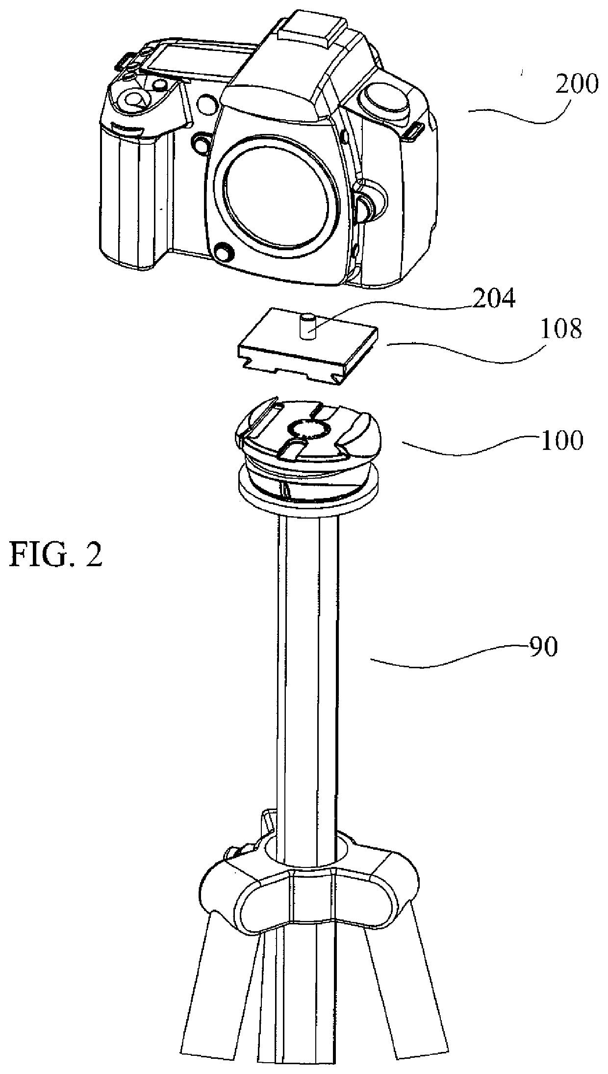
[0029]FIGS. 2, 3 and 4, show a clamping apparatus 100, embodying the invention, mounted on a tripod 90. The clamping apparatus 100 can be used to clamp a base plate 108 to which a camera 200 can be attached.

[0030]FIG. 2 is an exploded view showing the clamping mechanism 100 mounted on a tripod 90 and a view of the base plate 108 and a camera 200 to be assembled together.

[0031]FIG. 3 shows the base plate 108 of FIG. 2 inserted within the clamping mechanism 100, to illustrate how the base plate 108 is coupled to the clamping mechanism 100. A camera 200 which would be attached to and mounted on the base plate 108 is not shown in this figure since it would hide the mounting of the base plate 108 to the clamping mechanism 100.

[0032]FIG. 4 shows a camera 200 mounted on the base plate 108 of FIG. 3 attached to the clamping mechanism 100. The base plate 108 is not seen clearly in this drawing as it sits below the camera.

[0033]The clamping apparatus 100, as shown in the Figures and as furthe...


PUM


Abstract

Clamping apparatus for a camera mount includes two clamping jaws slidably coupled to each other so they can move towards or away from each other along a common plane. A rotatable jaw movement controlling mechanism having an eccentric (elliptical or variable contour) shaped inner surface is coupled around a portion of the two clamping jaws for controlling the movement of the two clamping jaws towards or away from each other. A ratcheting mechanism is coupled to the jaw movement controlling mechanism for preventing slippage of the two clamping jaws when the two clamping jaws are moving towards each other. The ratcheting mechanism may include a release button for releasing the ratcheting function and enabling the jaws to move away from each other quickly and without much effort.

Description

[0001]This invention claims priority based on a provisional application bearing Ser. No. 62 / 788,956 titled CLAMP FOR CAMERA MOUNT filed Jan. 7, 2019 whose teachings are incorporated herein by reference.BACKGROUND OF THE INVENTION[0002]This invention relates to a clamping apparatus and more particularly to clamping apparatus which does not require a knob-screw or a clasp for performing a clamping function. More particularly, the invention relates to non-screw knob (or clasp-less) clamping apparatus which can be attached to and between (a) a camera stabilizing equipment (e.g., a tripod, ball mount or any other camera stabilizing equipment; and (b) a base plate (such as an ARCA plate) to which a camera may be attached, or any suitable item to be clamped.[0003]Prior art FIGS. 1A, 1B and 1C, show a known clamp 300 attached to a ball mount (tripod head) 302 via a screw 304. The clamp 300 includes two jaws (303, 303b) and a knob screw 306 which is used to secure (tighten) or release (loose...

Claims


Application Information

Patent Timeline
IPC IPC(8): G03B17/56F16M11/04F16B2/12F16M11/08
CPCF16M11/041F16M11/08F16B2/12G03B17/561F16M2200/024
Inventor TIEFENBRUNN, LARRY JSWASEY, MERIN
Owner TIEFENBRUNN LARRY J
Why Eureka
Try Eureka