Battery module

Active Publication Date: 2020-07-09
SANYO ELECTRIC CO LTD
View PDF0 Cites 3 Cited by
  • Summary
  • Abstract
  • Description
  • Claims
  • Application Information

AI Technical Summary

Benefits of technology

The present invention relates to a battery module with improved stability and reliability. The battery module includes a plurality of batteries with discharge valves, a battery holder, and a lead plate. The lead plate is connected to the batteries through a double-sided tape and a sealing label. The sealing label prevents potting resin from flowing inside through the outlet of the batteries. The battery module is designed to allow the lead plate to be stably and reliably connected to the batteries while preventing the potting resin from flowing inside through the outlet. The battery module is efficient to manufacture and has increased adhesive strength for the lead plate.

Problems solved by technology

This is because the potting resin that has flowed inside hinders proper operation of the discharge valve.

Method used


Image

  • Battery module
  • Battery module
  • Battery module

Examples


Embodiment Construction

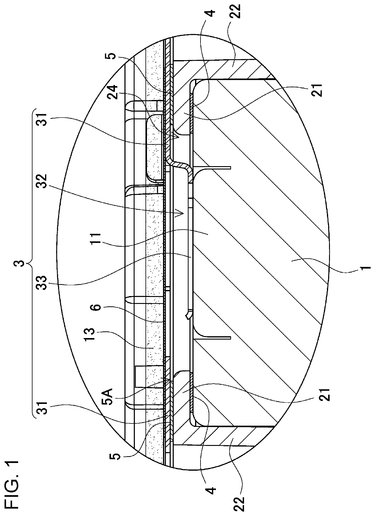
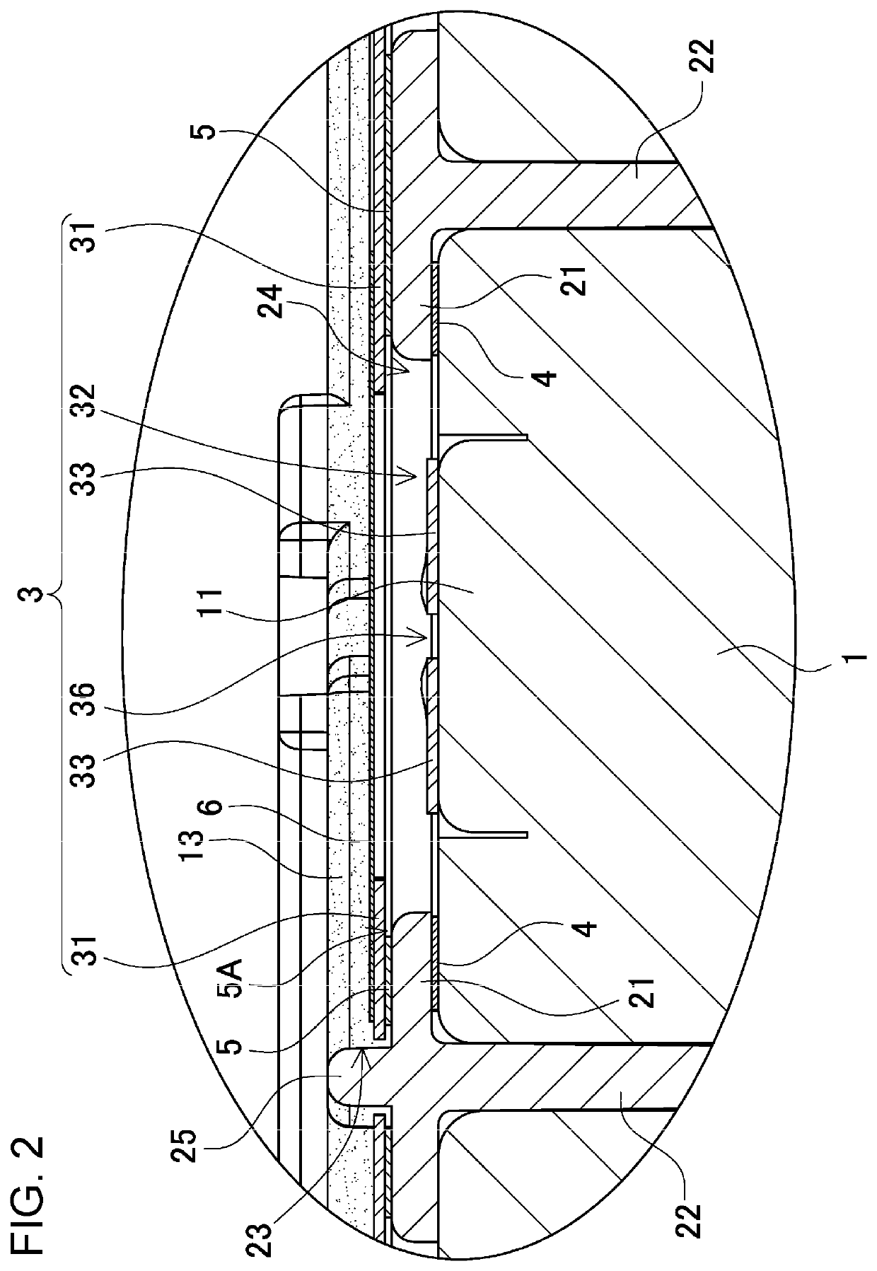
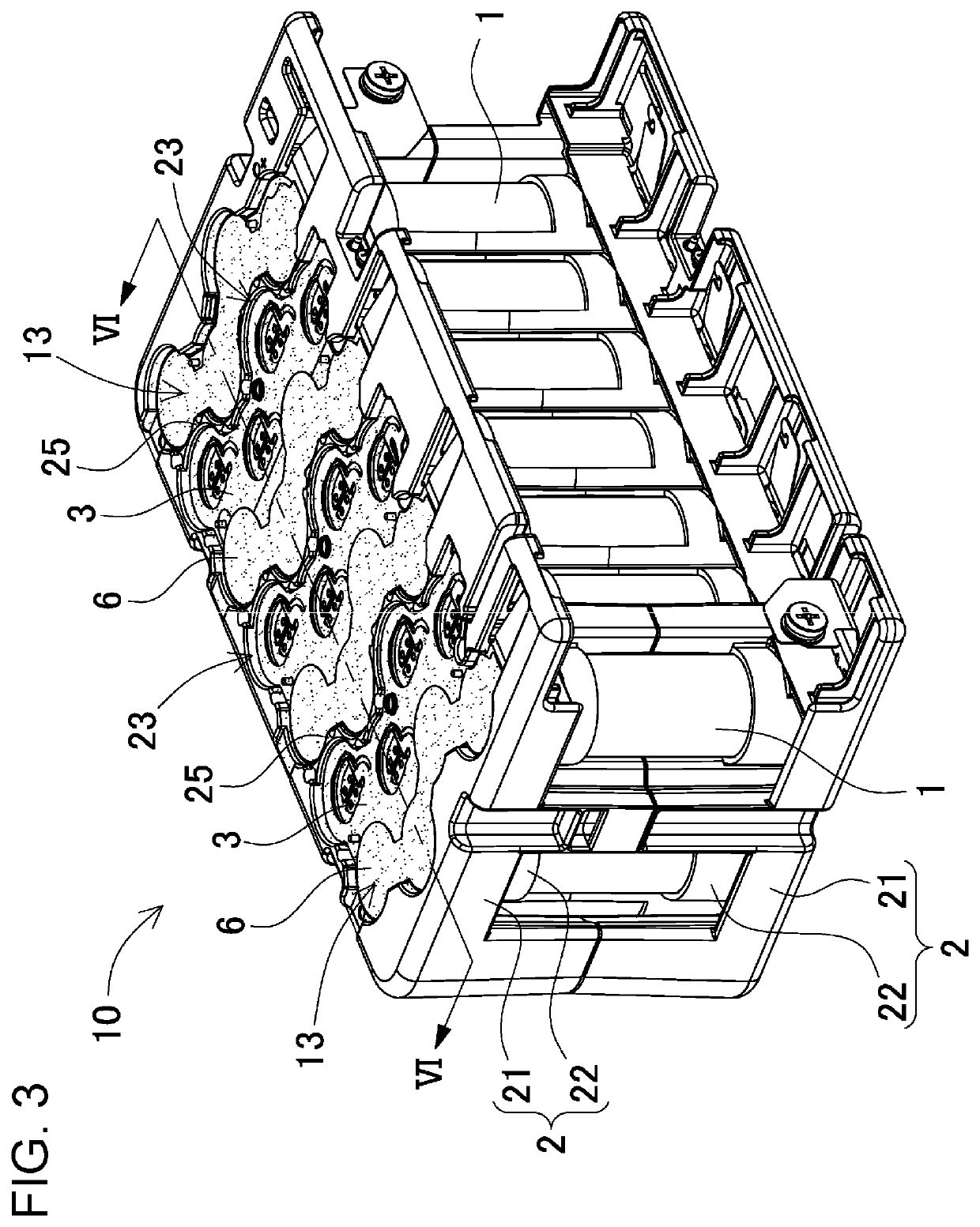
[0026]Hereinafter, an exemplary embodiment of the present invention will be described with reference to the drawings. It is to be noted, however, that the exemplary embodiment described below is an illustration embodying a technical idea of the present invention, and the present invention is not specifically limited to the following exemplary embodiment. The components recited in the claims are not limited to the components described in the exemplary embodiment. In particular, it is not intended to limit the scope of the present invention to sizes, materials, shapes, relative arrangement, and the like of the components, which are described in the exemplary embodiment, unless otherwise specified. The sizes and the like are mere explanation examples. The sizes, the relative positions, and others of the members may be illustrated exaggeratedly in the drawings for clear explanation. Furthermore, in the following description, the same names or the same reference marks denote the same com...


PUM


Abstract

The battery module has a structure in which a plurality of batteries are arranged at fixed positions by a battery holder, a lead plate is connected to a projecting electrode of each of the batteries, a potting resin is thermally coupled to the lead plate, the battery holder includes an outer peripheral cover having an electrode window to expose the projecting electrode, the lead plate has a connection recess that is locally formed in a planar part to let a protrusion face protrude toward the projecting electrode through the electrode window, and a sealing label is put into intimate contact with the planar part of the lead plate to close an opening of the connection recess. This structure prevents the potting resin from flowing into an outlet formed in the projecting electrode.

Description

TECHNICAL FIELD[0001]The present invention relates to a battery module in which a projecting electrode side of a battery is thermally coupled to a potting resin, and particularly to a battery module including a discharge valve disposed on a projecting electrode side of a battery.BACKGROUND ART[0002]A battery module in which a projecting electrode side of a battery is thermally coupled to a potting resin has been developed (see PTL 1).[0003]A battery module having this structure allows adjacent batteries to be thermally coupled to each other through a potting resin and thus is characterized by being able to reduce unevenness in temperatures of the batteries arranged at fixed positions. Each of the batteries with an outlet of a discharge valve formed in a projecting electrode is required to prevent the potting resin from flowing inside through the outlet when an end of the battery is buried under the potting resin. This is because the potting resin that has flowed inside hinders prope...

Claims


Application Information

Patent Timeline
IPC IPC(8): H01M2/26H01M2/04H01M2/10H01M2/34H01M50/213H01M50/50H01M50/503H01M50/514H01M50/528
CPCH01M2/0408H01M2/266H01M2/1077H01M2/345Y02E60/10H01M50/213H01M50/30H01M50/50H01M50/528H01M50/578H01M50/514H01M50/503
Inventor HAINO, MASAMIMURAMATSU, KOICHIFUKUSHIMA, KOUJI
Owner SANYO ELECTRIC CO LTD
Why Eureka
Try Eureka