Antenna module

a technology of antenna module and antenna, applied in the direction of antenna details, antennas, electrical equipment, etc., can solve the problems of lowering workability, lowering the quality of the sound source, so as to prevent the interference of the electrode in the magnetic permeability of the base substrate, preventing interference, and preventing the quality factor (q) of the antenna from being lowered

Active Publication Date: 2020-07-09
AMOTECH
View PDF3 Cites 0 Cited by
  • Summary
  • Abstract
  • Description
  • Claims
  • Application Information

AI Technical Summary

Benefits of technology

[0019]According to the present disclosure, the antenna module and the method of manufacturing the same may interpose the insulating substrate between the base substrate and the electrode to separate the base substrate and the electrode, thereby preventing the interference by the electrode in the magnetic permeability of the base substrate.
[0020]Further, the antenna module and the method of manufacturing the same may interpose the insulating substrate between the base substrate and the electrode to separate the base substrate and the electrode, thereby preventing the interference by the electrode in the magnetic permeability of the base substrate to prevent the Quality Factor (Q) of the antenna from being lowered.
[0021]Further, the antenna module and the method of manufacturing the same may adjust the thickness of the insulating substrate interposed between the base substrate and the electrode to adjust the separation interval between the base substrate and the electrodes, thereby enhancing the Quality Factor (Q) of the antenna to maximize the antenna performance.

Problems solved by technology

The wireless ear module has been mounted with a Bluetooth antenna for performing Bluetooth type wireless communication, but there is a problem in that if a portion of the user's body is disposed between the wireless ear module and the sound source device in the Bluetooth antenna, the quality of the sound source is lowered or the playback of the sound source is interrupted, or the like.
However, there are problems in that since the wireless ear module has a very narrow mounting space (working space), workability is lowered when the NFMI antenna is mounted, a yield is lowered due to poor workability, antenna performance is lowered, and the like.
However, there is a problem in that since the conventional SMD antenna 10 directly prints the metal paste on the ferrite sintered body 11, the interference by the metal paste occurs in the magnetic permeability of the ferrite sintered body 11, thereby lowering a Quality Factor (Q), which is a value that is much affected by the magnetic permeability of the ferrite sintered body 11.
Further, there is a problem in that since the conventional SMD antenna 10 is a structure in which the electrode 13 (that is, the metal paste) directly contacts the ferrite sintered body 11, the interference occurs in the magnetic permeability of the ferrite sintered body 11, thereby lowering the Quality Factor (Q) to lower antenna performance.

Method used


Image

  • Antenna module
  • Antenna module
  • Antenna module

Examples


first embodiment

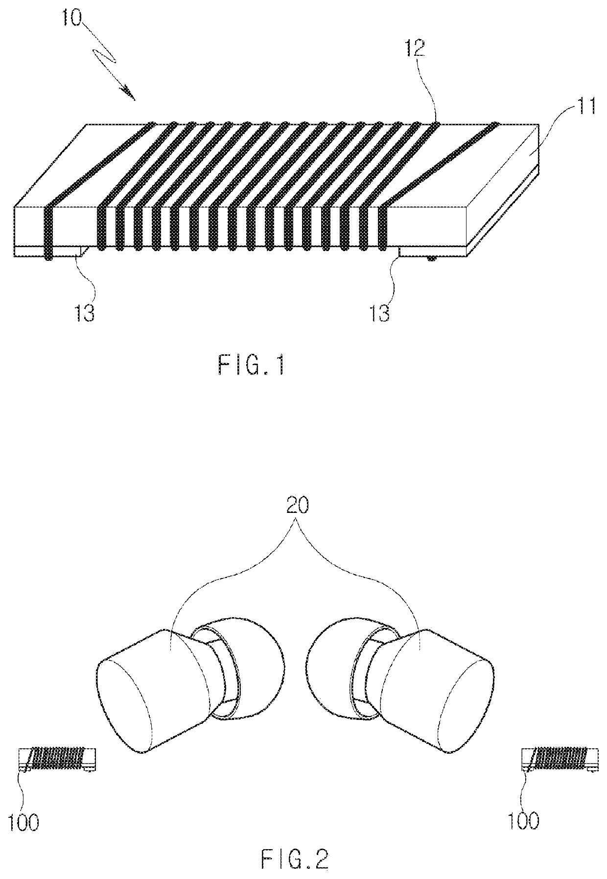
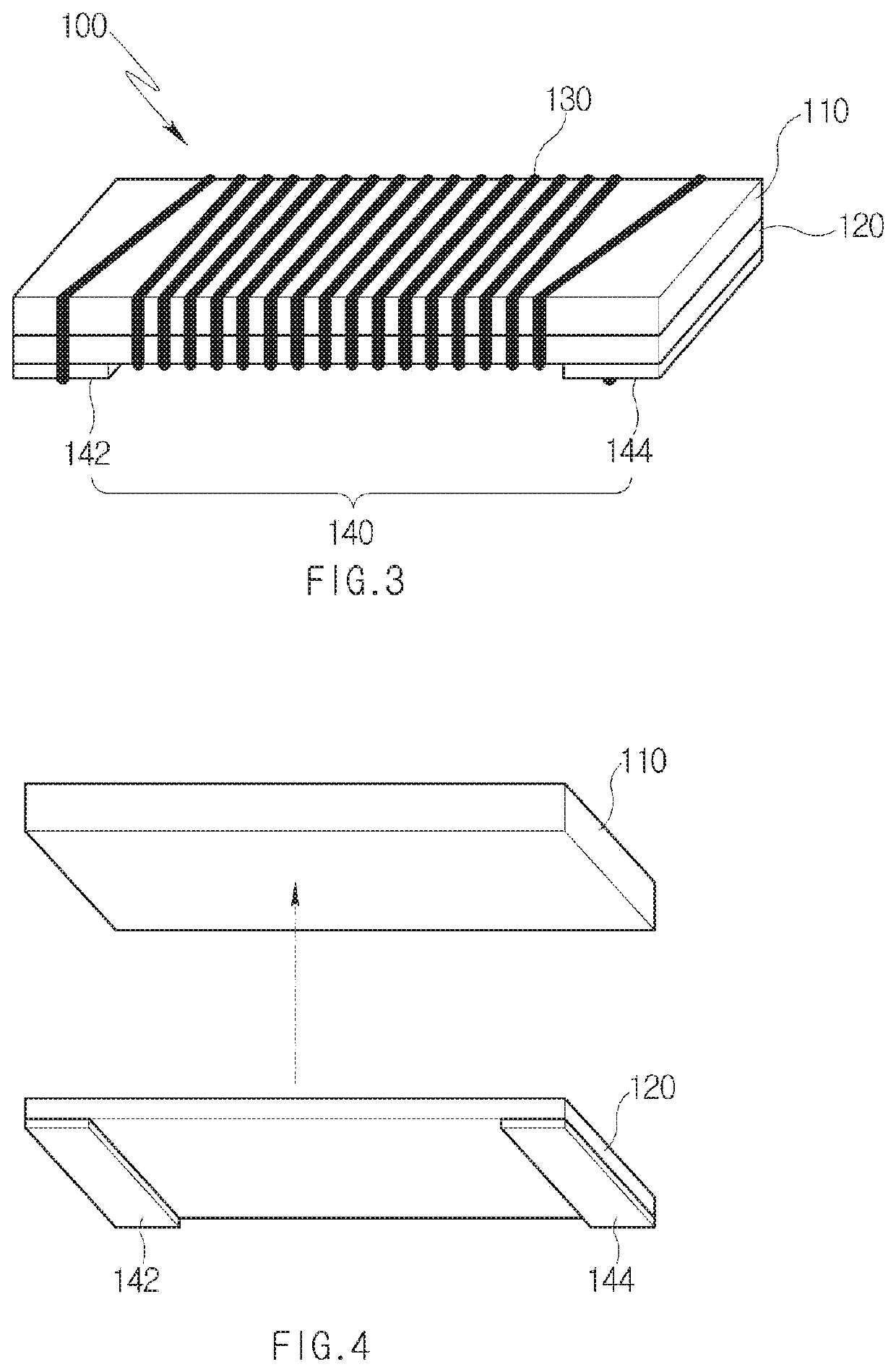
[0030]Referring to FIGS. 3 and 4, the antenna module 100 according to the present disclosure is configured to include a base substrate 110, an insulating substrate 120 disposed under the base substrate 110, and a radiation wire 130 wound around the base substrate 110 and the insulating substrate 120.

[0031]The base substrate 110 is formed of a magnetic body substrate having magnetic permeability. At this time, the magnetic body substrate is, for example, a ferrite substrate of a rectangular parallelepiped shape having a predetermined thickness.

[0032]The base substrate 110 is formed of a rigid magnetic body substrate because the radiation wire 130 is wound thereon. At this time, the base substrate 110 may also be a flexible magnetic body substrate if the insulating substrate 120 is rigid.

[0033]The insulating substrate 120 is formed of an insulating substrate having a predetermined thickness. At this time, the insulating substrate 120 is formed of a flexible insulating substrate. Here,...

second embodiment

[0045]Referring to FIGS. 8 and 9, an antenna module 200 according to the present disclosure is configured to include a base substrate 210, an insulating substrate 220 disposed under the base substrate 210, and a radiation wire 230 wound around the base substrate 210.

[0046]The base substrate 210 is formed of a magnetic body substrate having magnetic permeability. At this time, the magnetic body substrate is, for example, a ferrite substrate of a rectangular parallelepiped shape having a predetermined thickness.

[0047]The base substrate 210 is formed of a rigid magnetic body substrate because the radiation wire 230 is wound thereon. At this time, the base substrate 210 may also be a flexible magnetic body substrate if the first insulating substrate 222 is rigid.

[0048]The insulating substrate 220 is configured to include a first insulating substrate 222 and a second insulating substrate 224 formed separately.

[0049]The first insulating substrate 222 is formed of an insulating substrate h...


PUM

PropertyMeasurementUnit
thicknessaaaaaaaaaa
thicknessaaaaaaaaaa
thicknessaaaaaaaaaa

Abstract

Disclosed are an antenna module and a method for producing same, the antenna module having an insulating substrate interposed between a base substrate and electrodes so as to keep the base substrate apart from the electrodes and thereby prevent interference by the electrodes in the magnetic permeability of the base substrate. The disclosed antenna module comprises: a base substrate made of a magnetic material; an insulating substrate stacked on the lower surface of the base substrate; a first electrode disposed on the lower surface of the insulating substrate; a second electrode disposed, apart from the first electrode, on the lower surface of the insulating substrate; and a radiation wire which is wound around the base substrate and/or the insulating substrate and has one end thereof connected to the first electrode and the other end thereof connected to the second electrode.

Description

TECHNICAL FIELD[0001]The present disclosure relates to an antenna module for Near-field magnetic induction communication (NFMI) or near-field interaural communication, and more particularly, to an antenna module and a method of manufacturing the same, which are mounted to an ear module such as a wearable device, a hearing aid, or a wireless earphone to perform communication with the other device (for example, a wearable device, the main body of a hearing aid, or the other ear module).BACKGROUND ART[0002]An ear module is a device that plugs into his / her ears to allow him / her personally to listen to a sound source. The ear module may be classified into a wired ear module and a wireless ear module according to a connection method with a sound source device.[0003]The wireless ear module receives the sound source from the other ear module or the sound source device through wireless communication to output the sound source. For example, in the case of being applied to a wireless earphone,...

Claims


Application Information

Patent Timeline
Patent Type & Authority Applications(United States)
IPC IPC(8): H01Q7/06H01Q1/12
CPCH01Q7/06H01Q1/12H01Q7/08H01Q1/2283H01Q1/22
Inventor KIM, BEOM JINPARK, JONG HO
Owner AMOTECH
Why Eureka
Try Eureka