
Connector with guiding portion, and shell and insulating body of the same

Active Publication Date: 2020-07-09
AMPHENOL EAST ASIA TAIWAN BRANCH H K
View PDF2 Cites 0 Cited by
  • Summary
  • Abstract
  • Description
  • Claims
  • Application Information

AI Technical Summary

Benefits of technology

The present invention is a new type of connector that has a guiding portion to make it easier to connect and disconnect connectors. The connector has a metal shell and insulating body, where the metal terminals are fixedly provided. The metal shell is made by bending a metal plate and has a U-shaped cross section to create a space where the insulating body can be fixed. The guiding portion on the metal shell ensures accurate connection or disconnection of connectors, protecting them from damage due to improper operations. The technical effect of this invention is to improve the user experience and ease of connection and disconnection of connectors.

Problems solved by technology

One of the challenges facing automotive connectors is that two connected automotive connectors in a vehicle may eventually come loose, if not separate, from each other as a result of the vibrations generated by the vehicle running on bumpy roads.
Moreover, automotive connectors are generally compact in size to save space, but the fact that most of the space in a vehicle (particularly the passenger compartment) must be left vacant for the driver's or passengers' comfort requires that automotive connectors be disposed adjacent to other components of the vehicle, which makes it difficult to plug in and unplug those connectors.
In particular, if the location where two automotive connectors are to be connected is blocked from view, accurate connection of the connectors can be a problem, or a mechanic may pull one of the connectors away from the other in a wrong direction (e.g., slantingly) such that the internal components (e.g., the tongue plates or terminals) of the connectors are broken or otherwise damaged and lead to poor connector operation.

Method used


Image

  • Connector with guiding portion, and shell and insulating body of the same
  • Connector with guiding portion, and shell and insulating body of the same
  • Connector with guiding portion, and shell and insulating body of the same

Examples


Embodiment Construction

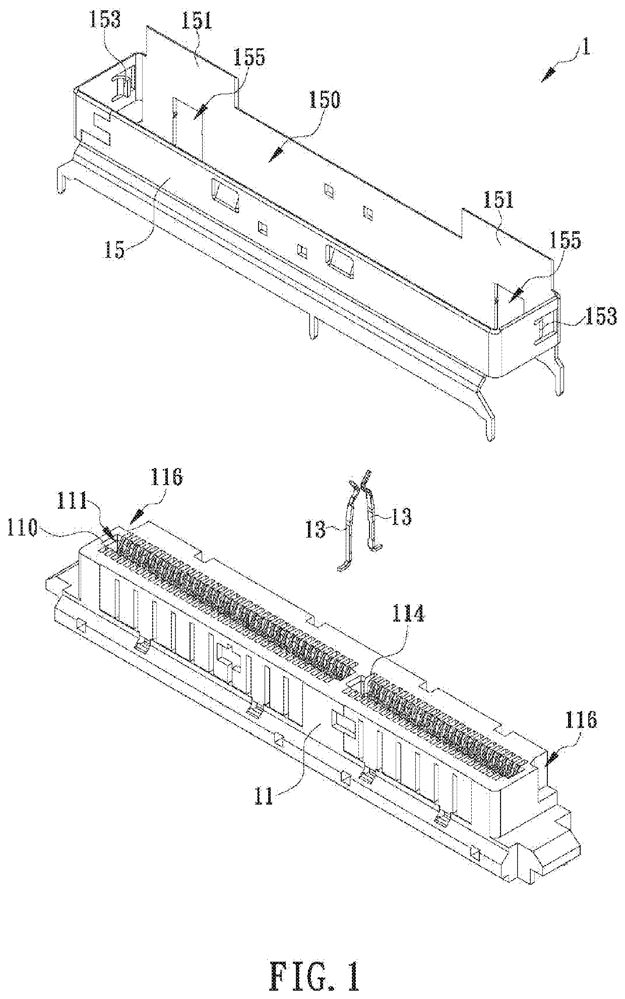
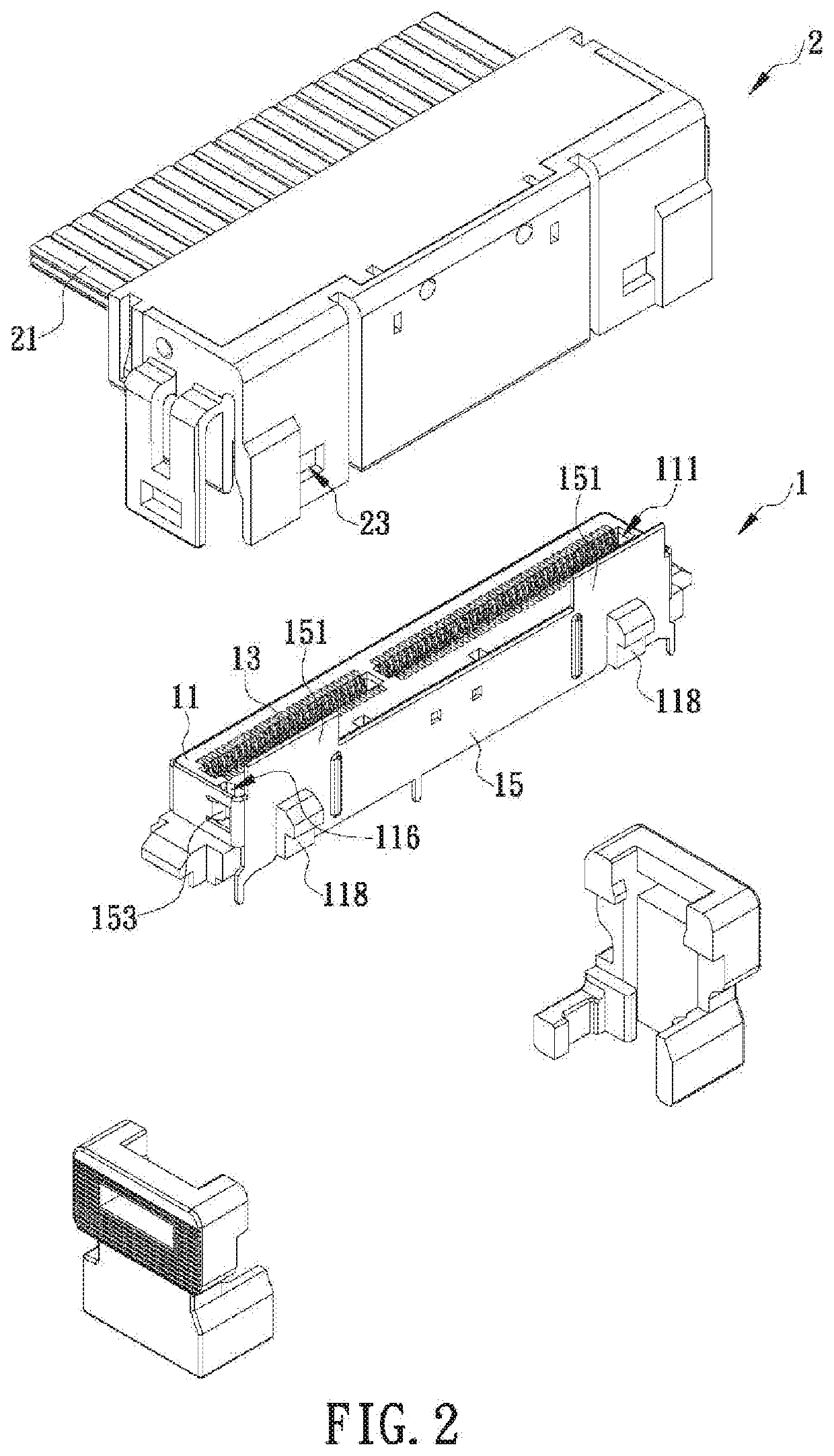
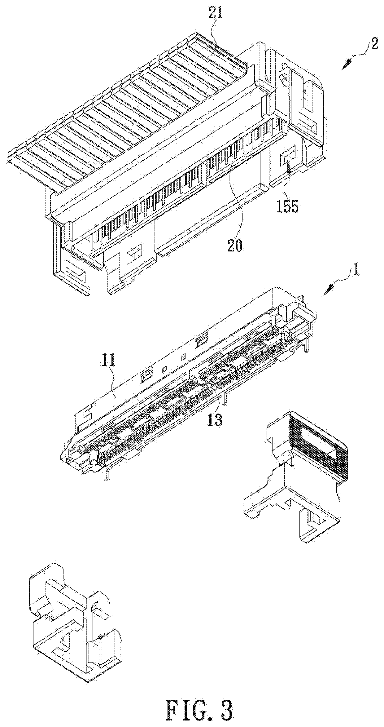
[0021]The present invention discloses a connector with at least one guiding portion and also discloses the shell and insulating body of the connector. In one embodiment of the invention as shown in FIG. 1 and FIG. 2, the connector 1 includes an insulating body 11, a plurality of metal terminals 13, and a shell 15. To facilitate description, the top side of each component of the connector 1 is defined as facing the top edge of FIG. 1, the bottom side of each component is defined as facing the bottom edge of FIG. 1, the left side of each component is defined as facing the upper left corner of FIG. 1, the right side of each component is defined as facing the lower right corner of FIG. 1, the front side of each component is defined as facing the lower left corner of FIG. 1, and the rear side of each component is defined as facing the upper right corner of FIG. 1. It should be pointed out that the configurations of the connector 1, the insulating body 11, and the shell 15 are not limited...


PUM


Abstract

A connector with at least one guiding portion is provided along with a shell and an insulating body of the connector. The connector includes a plurality of metal terminals in addition to the insulating body and the shell. The metal terminals are fixedly provided in the insulating body. The insulating body is mounted in the shell, and the connector is characterized in that at least one plate-shaped guiding portion extends upward from a portion of the top edge of either the shell or the insulating body. While another connector is being connected to or disconnected from the connector, the guiding portion guides the another connector to facilitate electrical connection with or detachment from the connector.

Description

FIELD OF THE INVENTION[0001]The present invention relates to a connector and more particularly to a connector whose shell or insulating body has a guiding portion so that the connector can be easily connected to another connector under the guidance of the guiding portion.BACKGROUND OF THE INVENTION[0002]Due to the advancement of electronic and communication technologies, electronic devices are nowadays equipped with a variety of functions and have become indispensable tools in our daily lives. Some notable examples of such devices are mobile phones, which allow people in different parts of the world to communicate with one another; powerbanks, which can be carried around to supply electricity to mobile phones continuously; portable audio players, which satisfy our need to listen to music anywhere anytime; and personal computers, which are depended upon to help with all sorts of things.[0003]In order to receive electronic signals and electric power from the outside, an electronic dev...

Claims


Application Information

Patent Timeline
IPC IPC(8): H01R13/516H01R13/631H01R13/627
CPCH01R13/631H01R13/516H01R13/627H01R12/716H01R13/6594
Inventor CHEN, CHIEN-MINGLIAO, SZU-TING
Owner AMPHENOL EAST ASIA TAIWAN BRANCH H K
Learn More