A Tool Holding Arrangement, Thread Insert, Rotatable Shaft and Drill Unit

Pending Publication Date: 2022-05-05
HUSQVARNA AB
View PDF0 Cites 0 Cited by
  • Summary
  • Abstract
  • Description
  • Claims
  • Application Information

AI Technical Summary

Benefits of technology

[0007]It is an object of the present disclosure to provide an easily managed and uncomplicated tool holding arrangeme

Problems solved by technology

However, such an arrangement has disadvantages where the tool holder can

Method used


Image

  • A Tool Holding Arrangement, Thread Insert, Rotatable Shaft and Drill Unit
  • A Tool Holding Arrangement, Thread Insert, Rotatable Shaft and Drill Unit
  • A Tool Holding Arrangement, Thread Insert, Rotatable Shaft and Drill Unit

Examples


Embodiment Construction

[0039]Aspects of the present disclosure will now be described more fully with reference to the accompanying drawings. The different devices disclosed herein can, however, be realized in many different forms and should not be construed as being limited to the aspects set forth herein. Like numbers in the drawings refer to like elements throughout.

[0040]The terminology used herein is for describing aspects of the disclosure only and is not intended to limit the invention. As used herein, the singular forms “a”, “an” and “the” are intended to include the plural forms as well, unless the context clearly indicates otherwise.

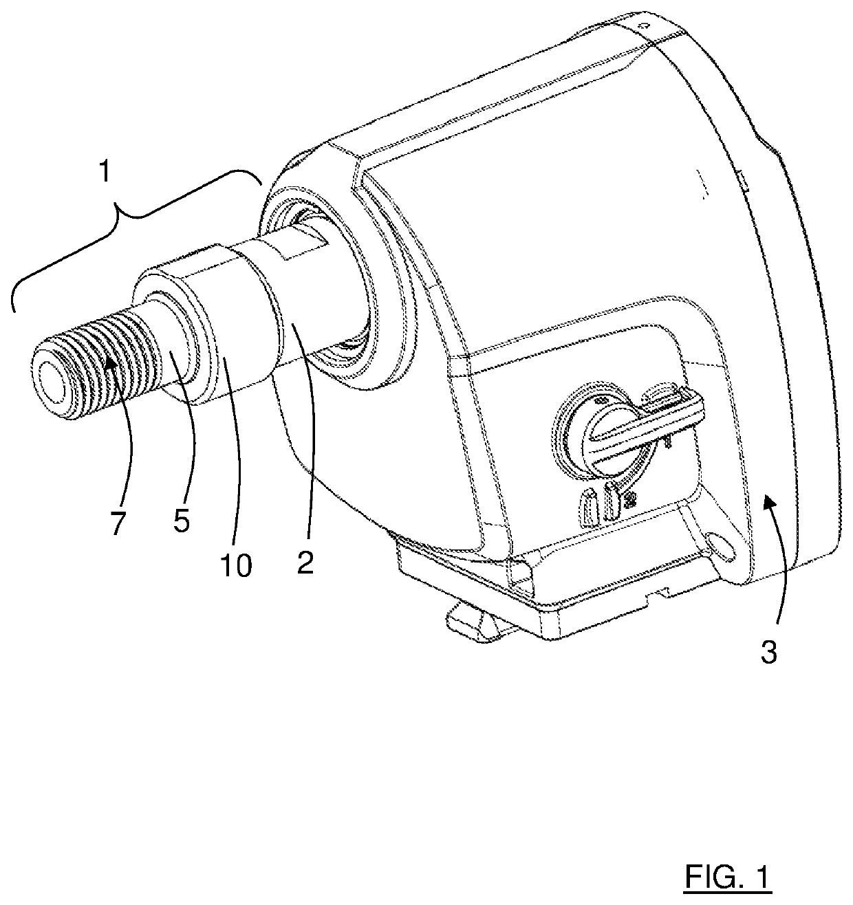
[0041]With reference to FIG. 1, showing a first example, there is a tool holding arrangement 1 that comprises a rotatable shaft 2 which here is shown connected to an electric tool driver 3. The electric tool driver 3, only shown partially, is of a conventional kind, and will not be further discussed here.

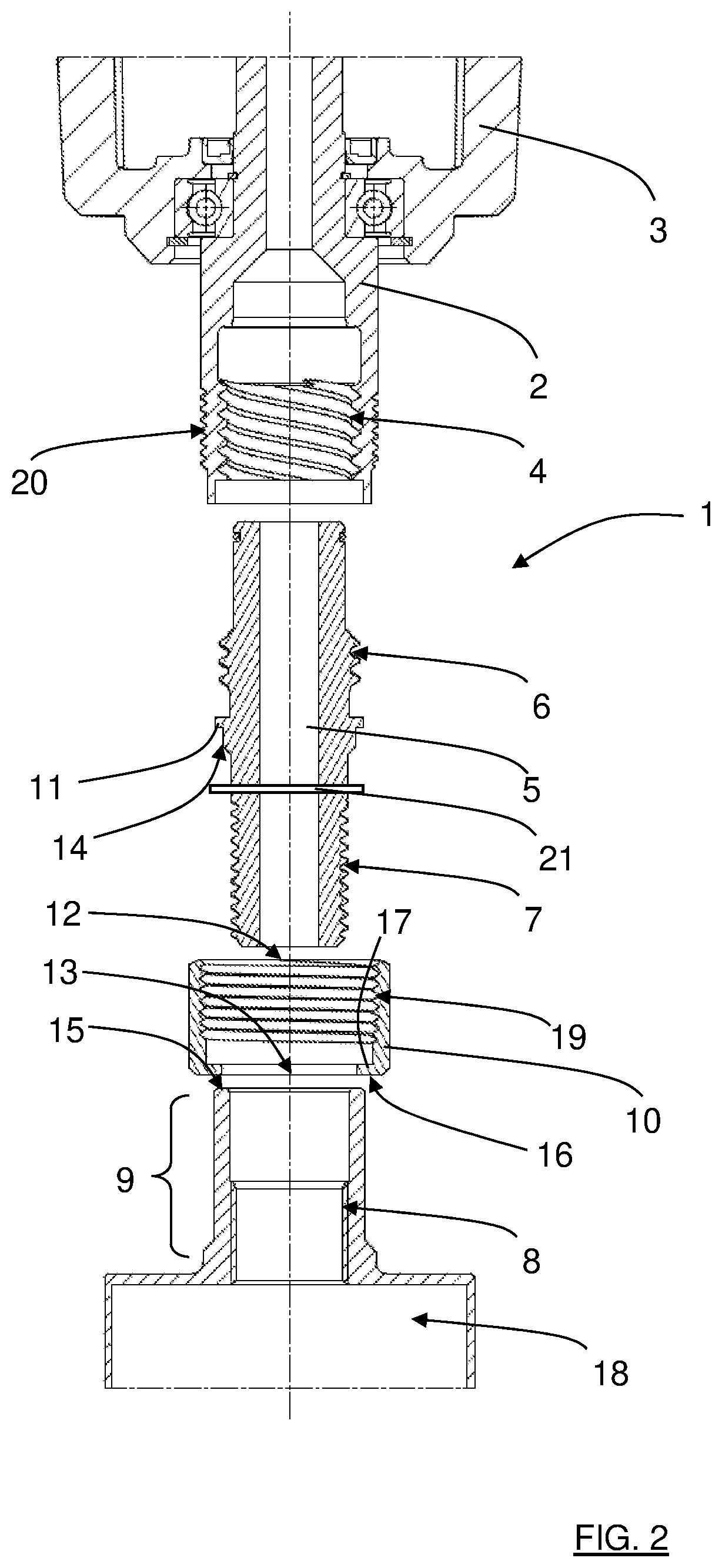
[0042]With reference also to FIG. 2, showing an exploded view of...


PUM

PropertyMeasurementUnit
Lengthaaaaaaaaaa
Lengthaaaaaaaaaa

Abstract

The present disclosure relates to a tool holding arrangement (1, 1′, 1″) comprising a rotatable shaft (2, 2′, 2″) which is at least connectable to a tool driving power source (3) and comprises a first shaft thread (4, 4′). The tool holding arrangement (1, 1′, 1) comprises a thread insert (5, 5′) that comprises a first insert thread (6, 6′), adapted to engage the first shaft thread (4, 4′) so as to form a first thread arrangement (4, 6; 4′, 6′). The thread insert (5, 5′) comprises a second insert thread (7) that is adapted to engage a tool thread (8) of a tool holding device (9) that is arranged to be 2 screwed onto the second insert thread (7) so as to form a second thread arrangement (7, 8), the first thread arrangement (4, 6; 4′, 6′) having a higher pitch than the second thread arrangement (7, 8).

Description

TECHNICAL FIELD[0001]The present disclosure relates to a tool holding arrangement comprising a rotatable shaft which is at least connectable to a drill unit and comprises a first shaft thread.BACKGROUND ART[0002]Construction machines are for example used when renovating, reconstructing and extending buildings. Drill motors with rotatable drive shafts are normally used for drilling holes, for example for piping in floors and walls of buildings. Tool holders are used for connecting a tool, such as a drill, to the drive shaft, where the tool is attached to the tool holder; for example by means of welding.[0003]The connection between a drive shaft and a tool holder is often made by means of threads, where the tool holder is screwed to the drive shaft. However, such an arrangement has disadvantages where the tool holder can be difficult to release from the drive shaft when a drill job is finished. Therefore, other types of connections between a drive shaft and a tool holder have been pro...

Claims


Application Information

Patent Timeline
IPC IPC(8): B23B31/11B23B51/04
CPCB23B31/1122B23B51/0473B23B31/11B23B45/003B23B2260/056B23C5/26B28D1/14
Inventor GRENNHAG, DAVID
Owner HUSQVARNA AB
Why Eureka
Try Eureka