Fluid filler opening system for a small planing boat

Active Publication Date: 2007-10-04
YAMAHA MARINE KK
View PDF3 Cites 0 Cited by
  • Summary
  • Abstract
  • Description
  • Claims
  • Application Information

AI Technical Summary

Benefits of technology

[0014]Because the fuel-receiving concave section can be formed around the filler opening, spilled fuel can be prevented from entering a storage section via the opening section. In addition, because the guide groove can be formed not in a side section of the opening section but in an outside section of the boat body, fuel spilled out of the filler opening can be guided in a down direction on an outside of the boat body while a sufficient size of the opening section can be ensured.
[0015]In another embodiment of the present invention, the fuel-receiving concave section is formed with a concave forming member that can be separate from a member of the deck. Since the concave section forming member having the fuel-receiving concave section can be formed as a member separate from the deck, it is not necessary to form the fuel-receiving concave section by processing the deck. This can increase the ease with which the deck may be manufactured and the fuel-receiving concave section may be formed.
[0016]In a further embodiment of the present invention, the concave forming member is configured to include a guide groove forming section having the guide groove, and the concave forming member including the guide groove forming section being configured to be molded in one piece as a member separate from the deck. Since the fuel-receiving concave section and the guide groove can be formed in one piece as a concave section forming member, the number of parts can be smaller than that of a case where the fuel-receiving section and the guide groove are formed se

Problems solved by technology

When the small planing boat is being filled while on the water or at another outside location, fuel being fi

Method used


Image

  • Fluid filler opening system for a small planing boat
  • Fluid filler opening system for a small planing boat
  • Fluid filler opening system for a small planing boat

Examples


Example

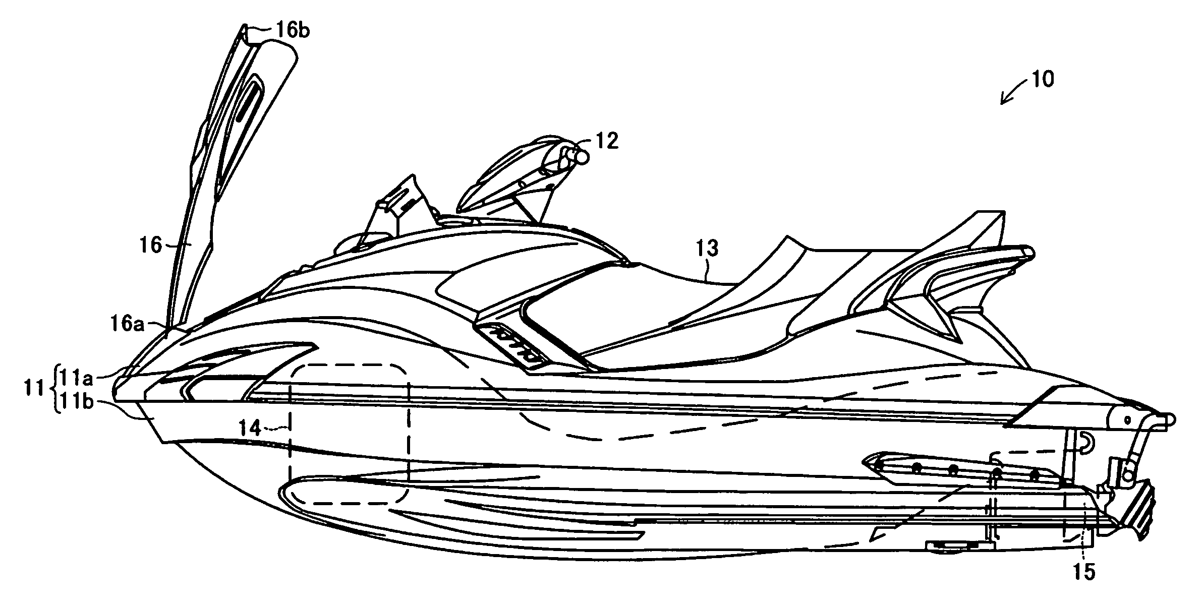
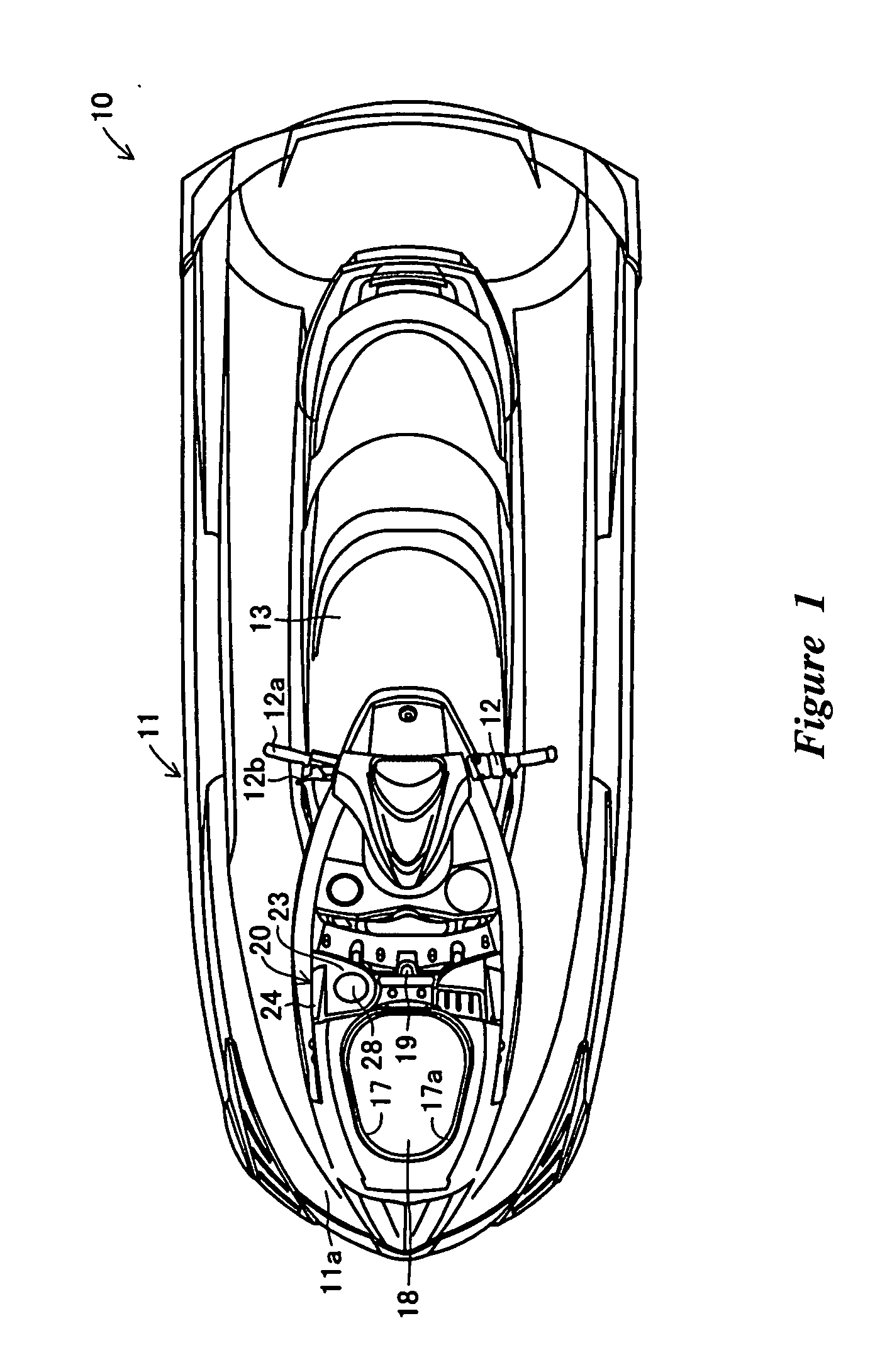
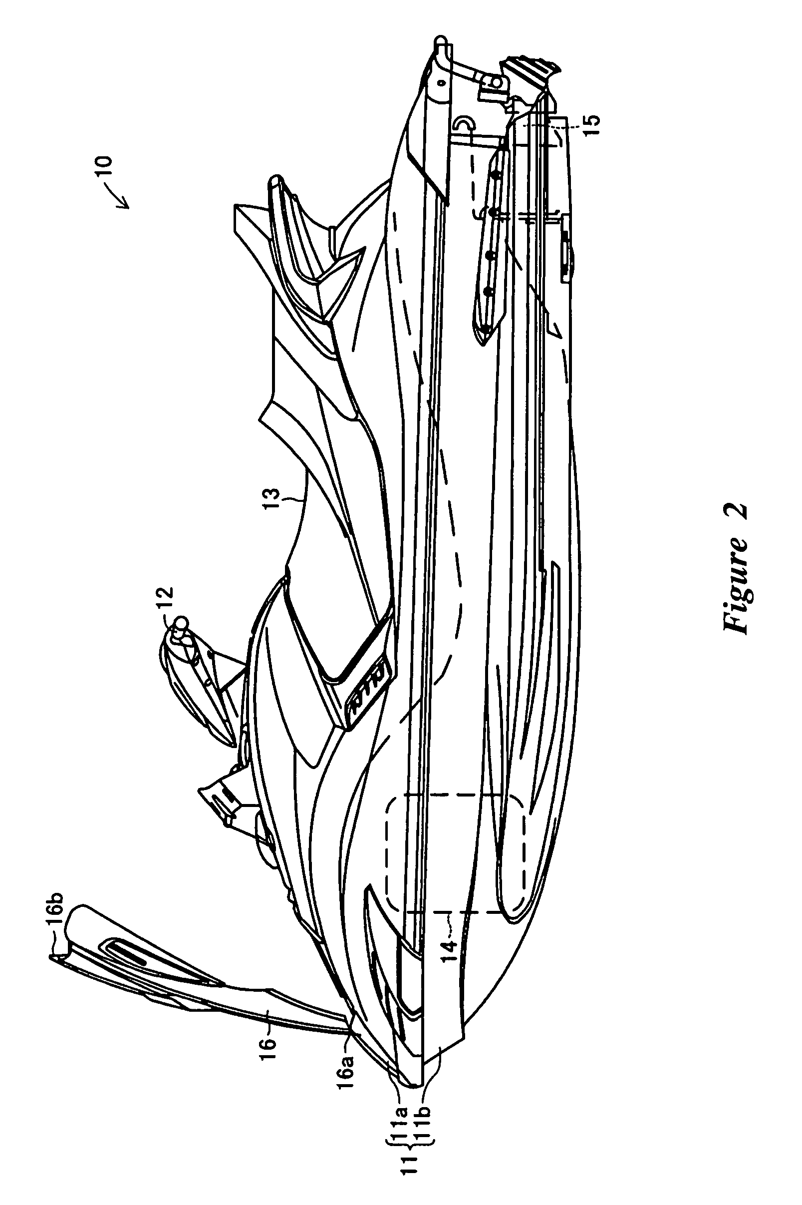
[0031]The following description explains a small planing boat according to an embodiment of the present invention in detail with reference to accompanying drawings.

[0032]As used through this description, unless indicated otherwise or otherwise readily apparent from the use in context, the terms “forward,”“front,” and “frontward” refer to a direction that is towards a front of the small planing boat or to a portion (such as a portion of a component) that is nearer to the front of the small planing boat. The term “rear,” unless indicated otherwise or otherwise readily apparent from the use in context, refers to a direction that is towards a rear of the small planing boat or to a portion (such as a portion of a component) that is nearer to the rear of the small planing boat. The terms “center” and “center side,” unless indicated otherwise or otherwise readily apparent from the use in context, refer to a direction that is towards an imaginary line that runs lengthwise along a center por...


PUM


Abstract

A small planning boat includes a filler opening for a fuel tank and an opening section that are formed on the deck of the boat body. The filler opening and the opening section are covered with a hatch cover when the hatch cover is closed. A fuel-receiving concave section is formed around the filler opening, so that the filler opening is positioned at the bottom surface section of a fuel-receiving concave section. A guide groove that declines downward from the bottom surface section on an outer side of the boat body can be formed as one piece with the fuel-receiving concave section. A storage section can also be formed inside the opening section. In addition, the filler opening can be positioned on the starboard side rearward from the opening section, and the guide groove can be formed in a section on an outer side of the opening section.

Description

PRIORITY INFORMATION[0001]The present application is based on and claims priority under 35 U.S.C. §119 to Japanese Patent Application Serial No. 2006-096721, filed on Mar. 31, 2006, the entire contents of which are expressly incorporated by reference herein.BACKGROUND OF THE INVENTION[0002]1. Field of the Invention[0003]The present invention relates to a small planing boat of which a filler opening can be covered with a hatch cover.[0004]2. Description of the Related Art[0005]Many small planing boats are propelled by taking in water, such as sea water, from a bottom of the boat by using a jet pump and by jetting the water out behind the stern to plane on the water. An example of such small planing boats is described in Japanese Publication No. P-A-2000-53091, which describes covering a filler opening used for filling an oil tank with a hatch cover to make the opening section invisible from the outside when the hatch cover is closed.[0006]However, in some conventional planing boats, ...

Claims


Application Information

Patent Timeline
IPC IPC(8): B63B35/73
CPCB63B19/00B63B35/731B63B25/082B63B34/10
Inventor KANEKO, YOSHIYUKI
Owner YAMAHA MARINE KK
Why Eureka
Try Eureka