

Three-dimensional Helicoidal Post-Tensioning and Reinforcement Strategy for Concrete Anchor Applications
- Summary
- Abstract
- Description
- Claims
- Application Information
AI Technical Summary
Benefits of technology
Problems solved by technology
Method used
Image

Examples
first embodiment
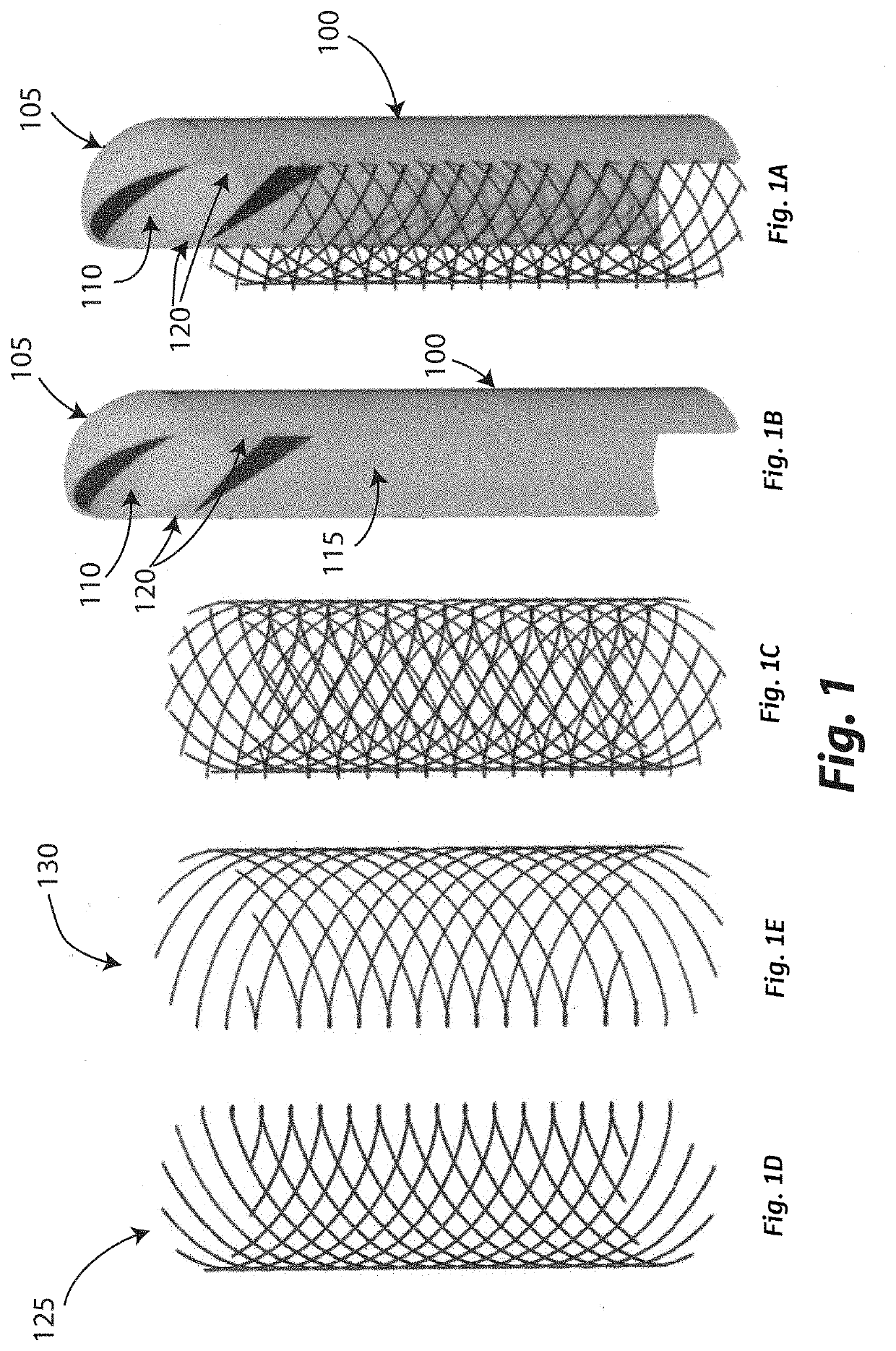
[0051]Making reference to FIG. 1, the concrete suction anchor according to the invention includes a cylindrical structure 100, open at a bottom end and closed by a top dome 105 at the top end. The top dome 105 defines an internal buoyancy chamber 110 having a substantially spherical shape. The internal buoyancy chamber 110 is separated from the main cavity 115 of the cylindrical structure 100 of the concrete suction anchor by a bottom surface provided with top stiffeners 120 evenly angularly distributed over the circular cross section of the cylindrical section 100, the top edge of which top stiffeners 120 follows the bottom surface of the internal buoyancy chamber 110. The lateral cylindrical wall of the concrete suction anchor, namely the lateral cylindrical wall of the cylindrical structure 100 thereof defining the main cavity 115 open at the bottom end, includes a plurality of internal channels housing a pair of sets of post-tensioning tendons: a first set of post-tensioning ten...
sixth embodiment
[0062]FIG. 6 shows the concrete suction anchor according to the invention differing from the forth embodiment shown in FIG. 4 in that the top dome 105 defines a top internal buoyancy chamber 180 having a substantially hemispherical shape with a substantially flat bottom surface 182, and in that the intermediate internal buoyancy chamber 184 has a substantially cylindrical shape and it is provided with thicker stiffener 188 parallel to the longitudinal axis of the concrete suction anchor which are still substantially orthogonal to each other. The top surface 186 of the main cavity 185 of the cylindrical structure 100 is also substantially flat.
second embodiment
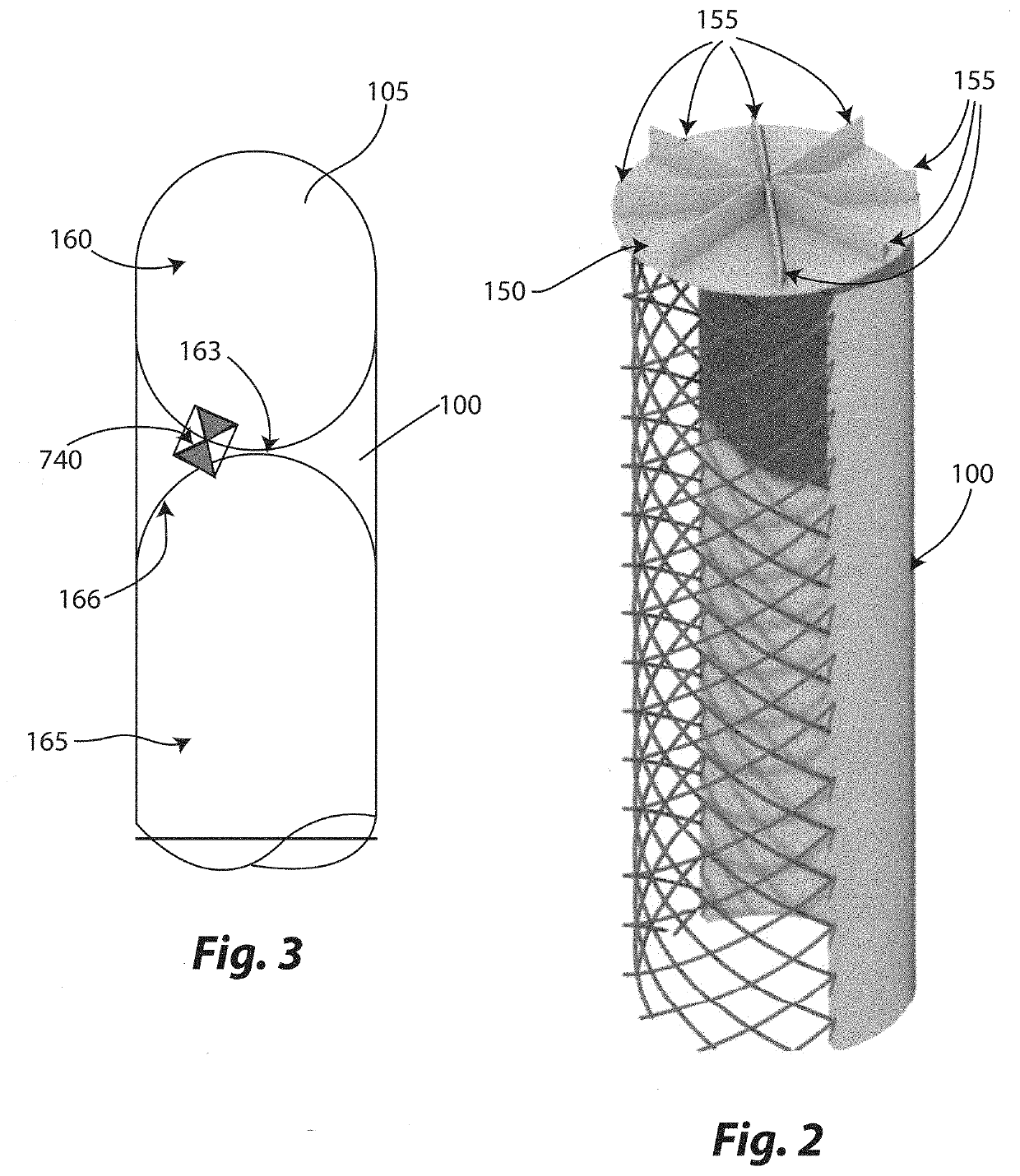
[0063]It must be noted that other embodiments of the concrete suction anchor according to the invention can be devoid of any internal buoyancy chamber, like in the second embodiment shown in FIG. 2, even in the case where the concrete suction anchor includes a top dome, still remaining within the scope of protection of the present invention.
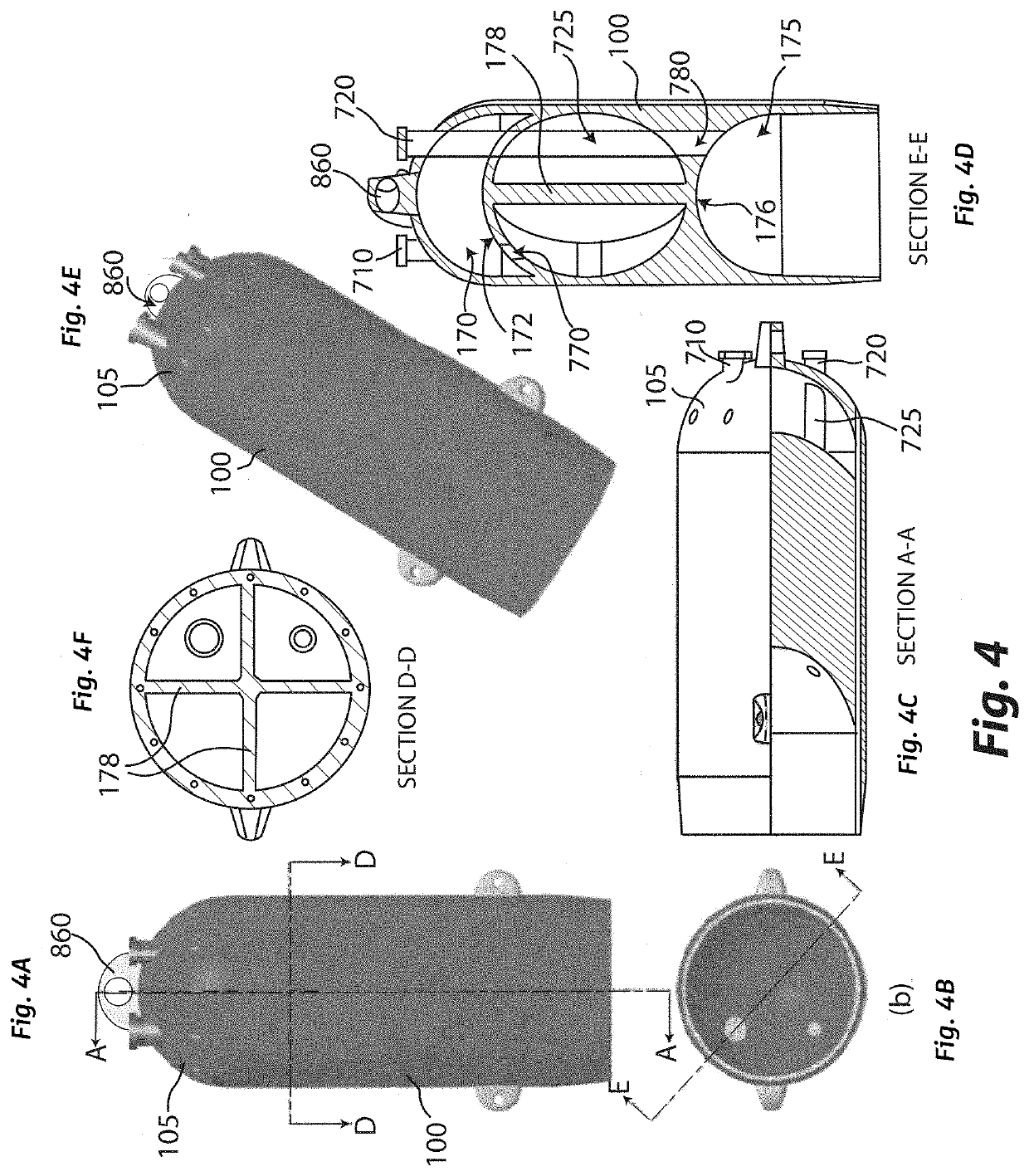
[0064]As schematically shown in FIG. 7, and also with reference to FIG. 4, the embodiments of the concrete suction anchor according to the invention including a top internal buoyancy chamber 700 have a first top valve 710, that is configured to put the top internal buoyancy chamber 700 in fluid communication with the external environment, a second top valve 720 that is configured to put the main cavity 730, acting as a suction chamber, of the cylindrical structure 100 in fluid communication with the external environment by means of a duct 725, and an internal vent 740 (not shown in FIG. 7, but schematically shown in FIGS. 3, 10a, 11 and 12} that ...
PUM
 Abstract
Description
Claims
Application Information