Support stand for combine feeder house

a technology for feeder houses and supports, applied in the direction of stands/trestles, lifting devices, agricultural tools and machines, etc., can solve the problems of time-consuming, dangerous, and difficult to maintain

Active Publication Date: 2020-07-23
WADSLEY ROBERT LESLIE
View PDF9 Cites 0 Cited by
  • Summary
  • Abstract
  • Description
  • Claims
  • Application Information

AI Technical Summary

Benefits of technology

[0005]Therefore, it is a primary object, feature, and / or advantage of the invention to improve on and / or overcome the deficiencies in the art.
[0006]According to one embodiment, the present invention is a feeder house support stand. The support stand includes a base portion adapted to rest on a flat surface such as a floor or the ground and an upright frame extending upwardly from the base portion. The upright frame includes a cross member at an upper portion of the upright frame adapted to engage a flange on the feeder house. A lower portion of the upright frame includes a pair of upright posts that support limit members. The limit members may be threaded members. The limit members are positioned to support a feeder house in a cantilevered position between the cross member and the limit members. The base may be adapted to receive tines of a lifting device, such as a forklift. A latching member may be provided on the support stand to be engaged by a latching mechanism of the feeder house to further secure the feeder house to the stand.
[0007]According to another embodiment a method for removing a feeder house from a combine and supporting the combine in a position where it is convenient to perform work on the feeder house, includes providing a stand, wherein the stand includes:a base, with a flat lower surface. The base is adapted to receive a lifting mechanism; An upright frame is mounted at a first end of the base. The upright frame is adapted to selectively attach to a feeder house on a combine when raised by the lifting mechanism into alignment with the feeder house. The lifting mechanism can move the feeder house attached to the upright frame to a desired location and lower the base until its flat lower surface rests on a support surface such as a floor or the ground. With the lower surface resting on the support surface the stand supports the attached feeder house in a secure configuration above the ground. The method further includes providing a lifting device that includes a lifting mechanism. The lifting device is positioned with the lifting mechanism in engagement received within the base and supporting the stand on the lifting device by raising the lifting mechanism. The upright frame member is then positioned adjacent to and into alignment with the feeder house by moving the lifting device supporting the stand. The feeder house is lifted off of the combine by raising the lifting mechanism to bring the adjacent aligned upright frame member into engagement with the feeder house. The lifted feeder house is moved by moving the lifting device away from the combine. The feeder house is then lowered by lowering the lifting mechanism until the base is supported on the ground after moving the lifted feeder house away from the combine.

Problems solved by technology

This is an awkward, time-consuming, and dangerous process.

Method used


Image

  • Support stand for combine feeder house
  • Support stand for combine feeder house
  • Support stand for combine feeder house

Examples


Embodiment Construction

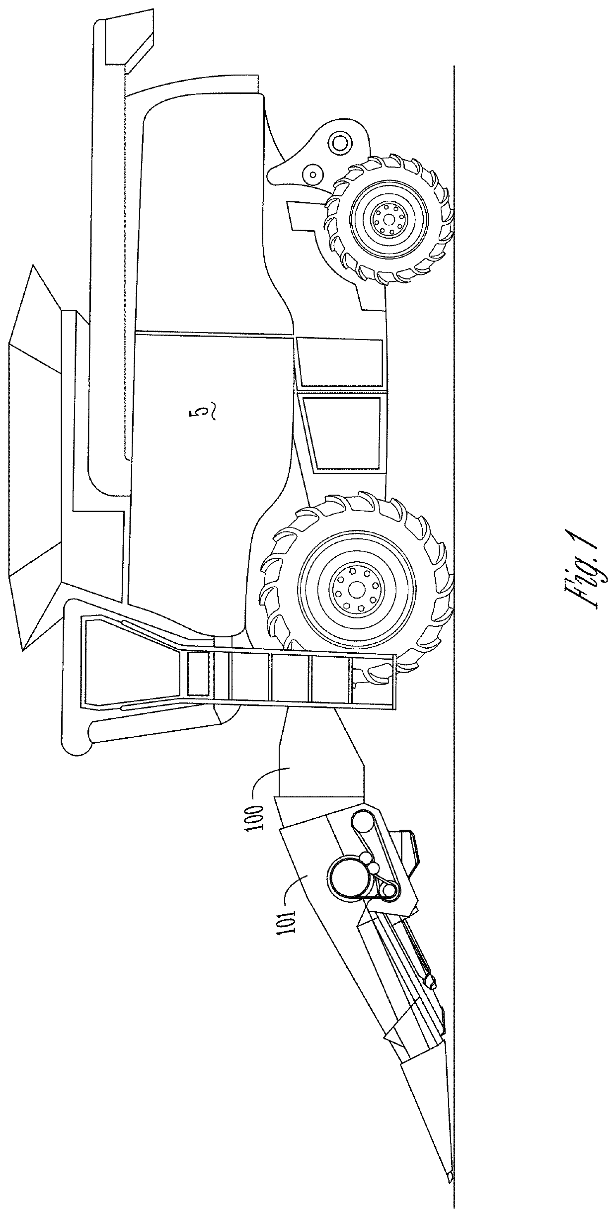
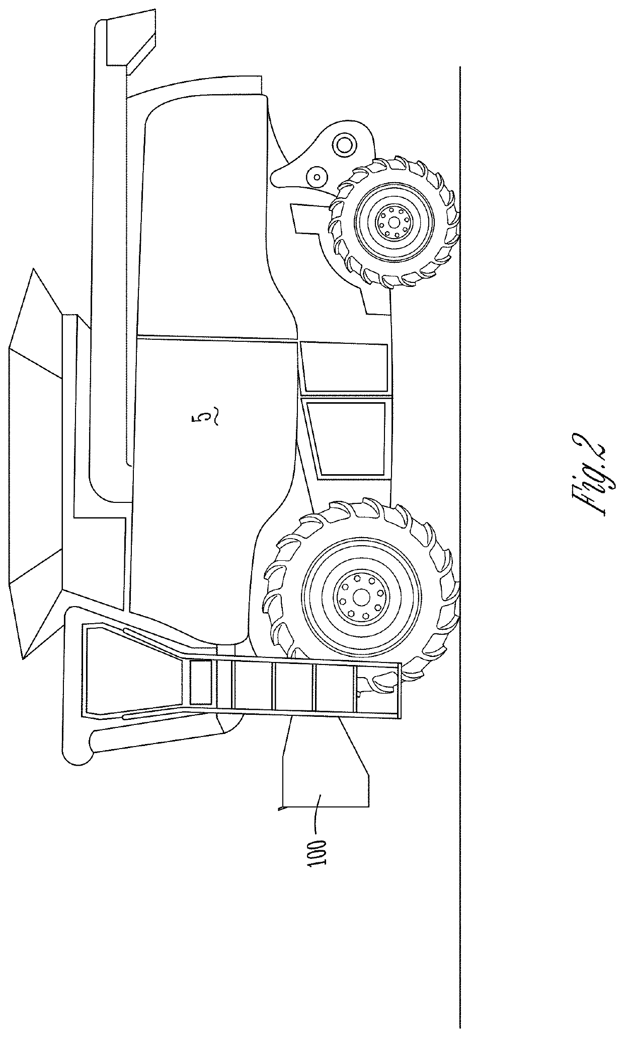
[0023]Shown generally in the figures is a support stand 10 that is used for removing, repairing, storing, and reattaching a feeder house 100 from an agricultural combine 5. The stand 10 is adapted to be raised and lowered with a forklift 200 to position the stand 10 adjacent to the feeder house 100 during removal and to position the feeder house 100 on the combine 5 during reattachment. Once the feeder house 100 is attached to the stand 10, the combination can be moved by a forklift 200 to any convenient location. The stand 10 can be set on the ground or a floor and will support the feeder house 100 so that it can be worked on safely for repair or maintenance. After the repair or maintenance, the stand 10 can be used to conveniently and safely reattach the feeder house 100 to the combine. Alternatively, the combination can be moved to a desired location for storage.

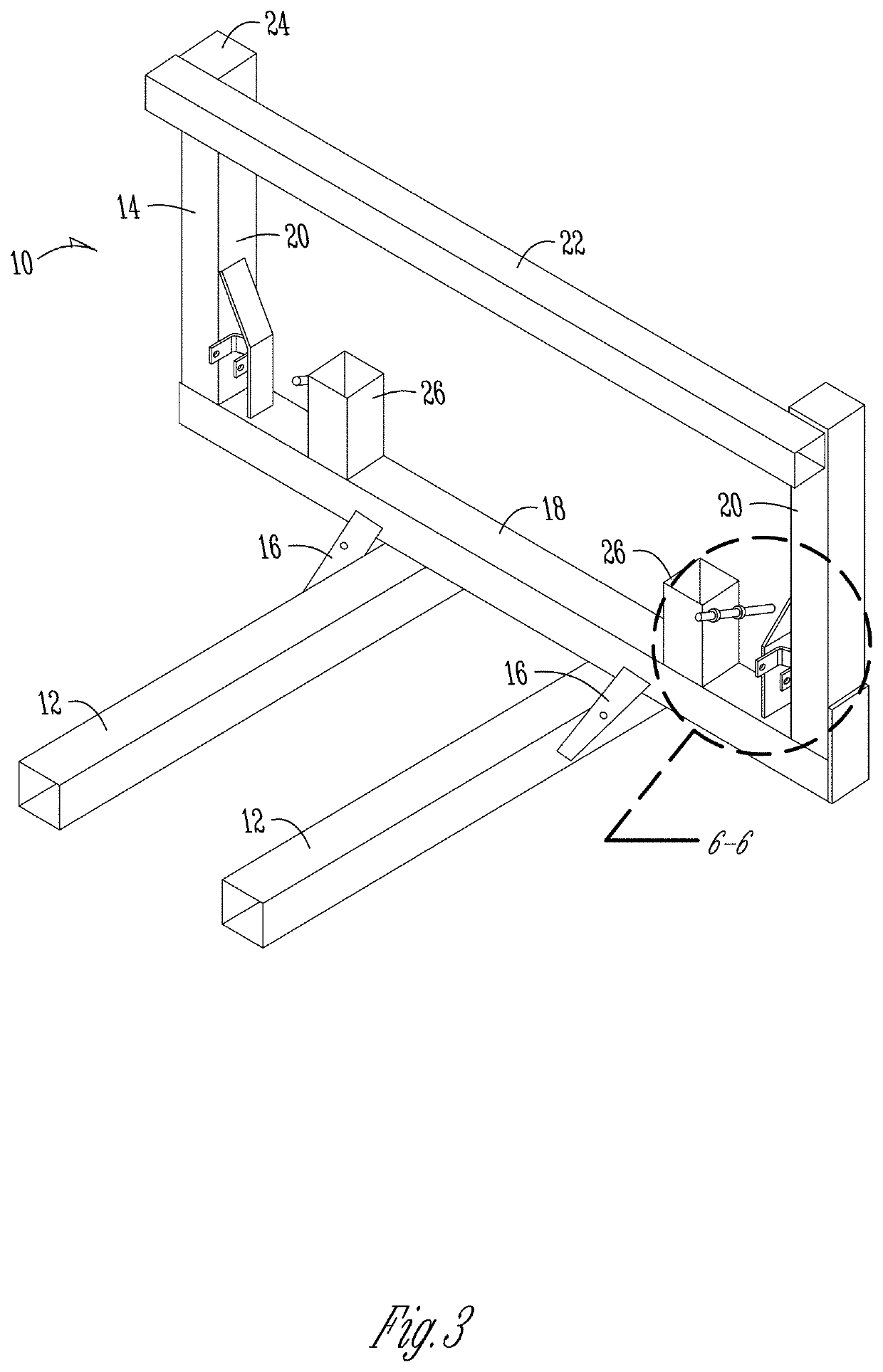
[0024]FIG. 3 is an isometric view of a support stand 10 according to one embodiment that includes features of the prese...


PUM


Abstract

A support stand is used for removing, repairing, storing, and reattaching a feeder house from an agricultural combine. The stand is adapted to be raised and lowered with a forklift to position the stand adjacent to the feeder house during removal and to position the feeder house on the combine during reattachment. The stand includes a base, the base having a flat lower surface, the base being adapted to receive a lifting mechanism. An upright frame is mounted at a first end of the base, the upright frame being adapted to selectively attach to a feeder house on a combine when raised by the forklift into alignment with the feeder house.

Description

CROSS REFERENCE TO RELATED APPLICATION[0001]This application claims priority under 35 U.S.C § 119 to provisional application Ser. No. 62 / 794,007 filed Jan. 18, 2019 the entire contents of which are hereby incorporated by reference.FIELD OF THE INVENTION[0002]The invention relates generally to maintenance and storage equipment for agricultural implements, and more specifically to a support stand for removing, supporting, and reattaching a combine feeder house.BACKGROUND OF THE INVENTION[0003]A feeder house is used to convey material from a harvesting header (sometimes referred to as a harvesting head) to a combine. Accordingly, the feeder house sits between the grain header and the combine when in use. Various types of headers may be attached and removed from the feeder house. Occasionally it is desirable to remove the feeder house from the combine for repair, maintenance, or storage. The conventional mechanism for removing a feeder house involves using a lifting device, such as a fo...

Claims


Application Information

Patent Timeline
Patent Type & Authority Applications(United States)
IPC IPC(8): A01D75/00F16M11/22
CPCA01D75/00F16M11/22A01D75/008B66F9/06B66F9/12
Inventor WADSLEY, ROBERT LESLIE
Owner WADSLEY ROBERT LESLIE
Why Eureka
Try Eureka