
Food delivery systems, apparatuses, and methods

a technology of food delivery and food containers, applied in the field of food containers, can solve the problems of ifcs being susceptible to moisture buildup, ifcs being subject to significant heat loss, and heat loss being particularly significant,

Pending Publication Date: 2020-07-23
GPCP IP HLDG LLC
View PDF0 Cites 19 Cited by
  • Summary
  • Abstract
  • Description
  • Claims
  • Application Information

AI Technical Summary

Benefits of technology

The patent describes a computer program that controls the temperature of a food chamber by adjusting the power supplied to a fan or heating element. The program can maintain the temperature of the chamber at a specific level or within a specific range. This allows for better control and management of the food chamber's temperature, which can improve food safety and quality.

Problems solved by technology

The technical problem addressed in this patent text is the potential for significant heat loss and moisture buildup in insulated food containers, which can affect the quality and freshness of the food products. This problem is particularly relevant in cold climates where the delivery distance and time of consumption may be longer.

Method used


Image

  • Food delivery systems, apparatuses, and methods
  • Food delivery systems, apparatuses, and methods
  • Food delivery systems, apparatuses, and methods

Examples


Embodiment Construction

[0080]Some example embodiments now will be described more fully hereinafter with reference to the accompanying drawings, in which some, but not all example embodiments are shown. Indeed, the examples described and pictured herein should not be construed as being limiting as to the scope, applicability or configuration of the present disclosure. Rather, these example embodiments are provided so that this disclosure will satisfy applicable legal requirements. Like reference numerals refer to like elements throughout. Furthermore, as used herein, the term “or” is to be interpreted as a logical operator that results in true whenever one or more of its operands are true.

[0081]As used in herein, the terms “component,”“module,” and the like are intended to include a computer-related entity, such as but not limited to hardware, firmware, or a combination of hardware and software. For example, a component or module may be, but is not limited to being, a process running on a processor, a proc...


PUM


Abstract

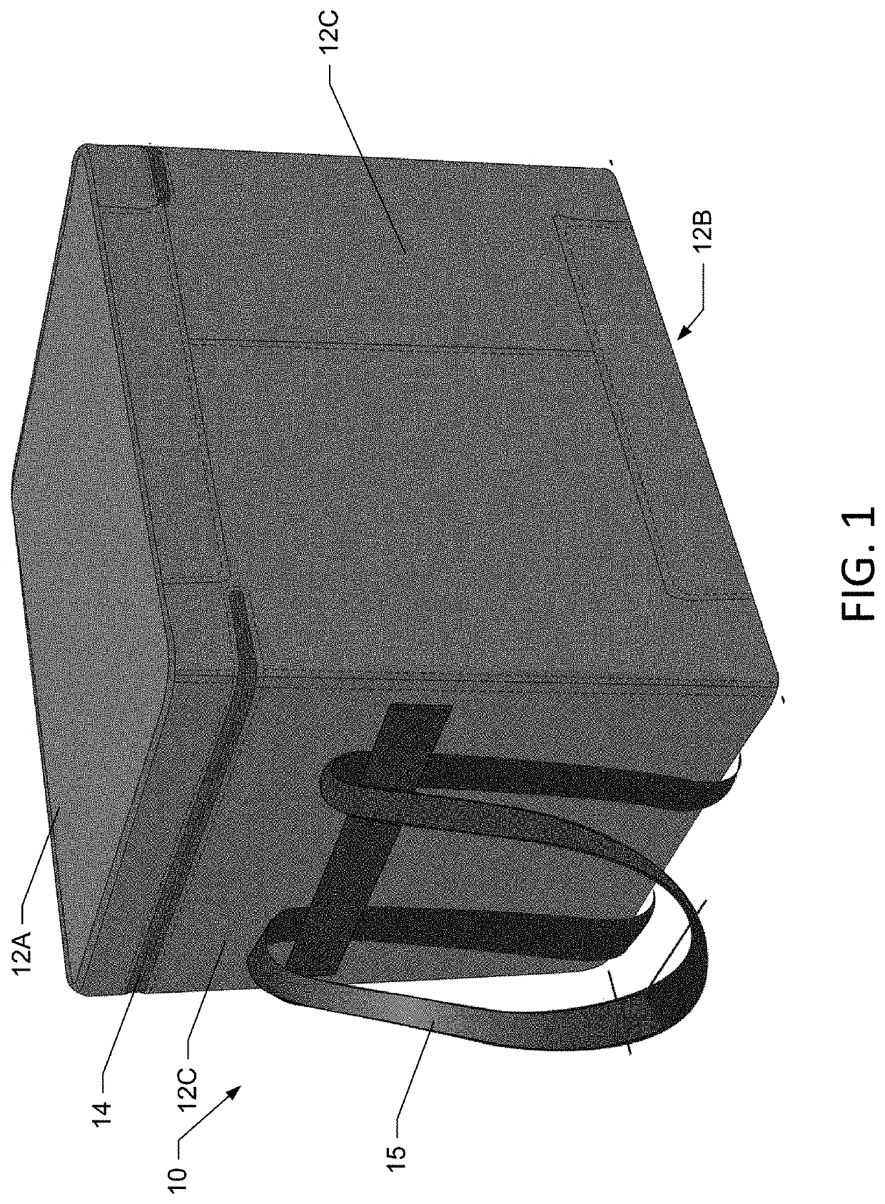
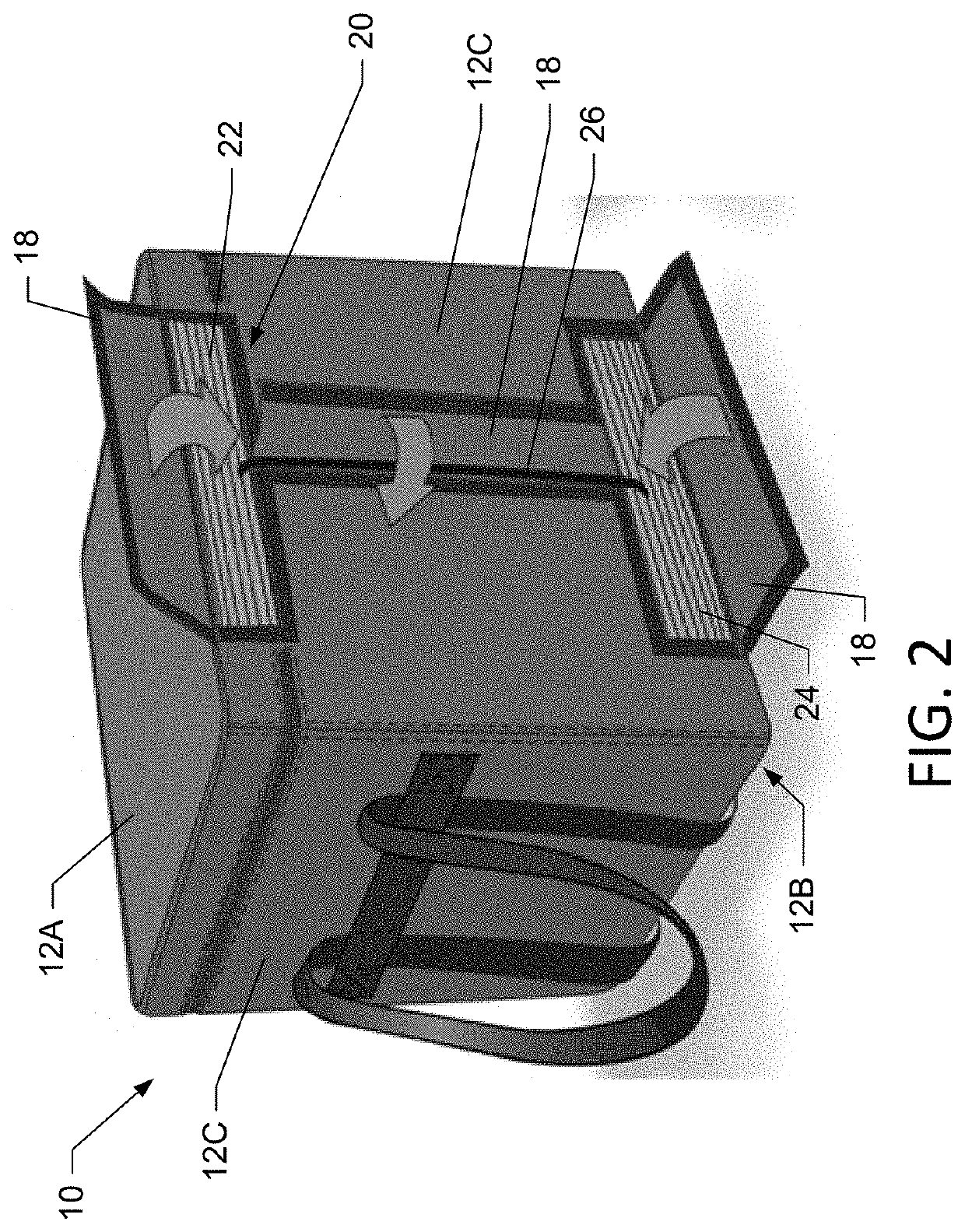
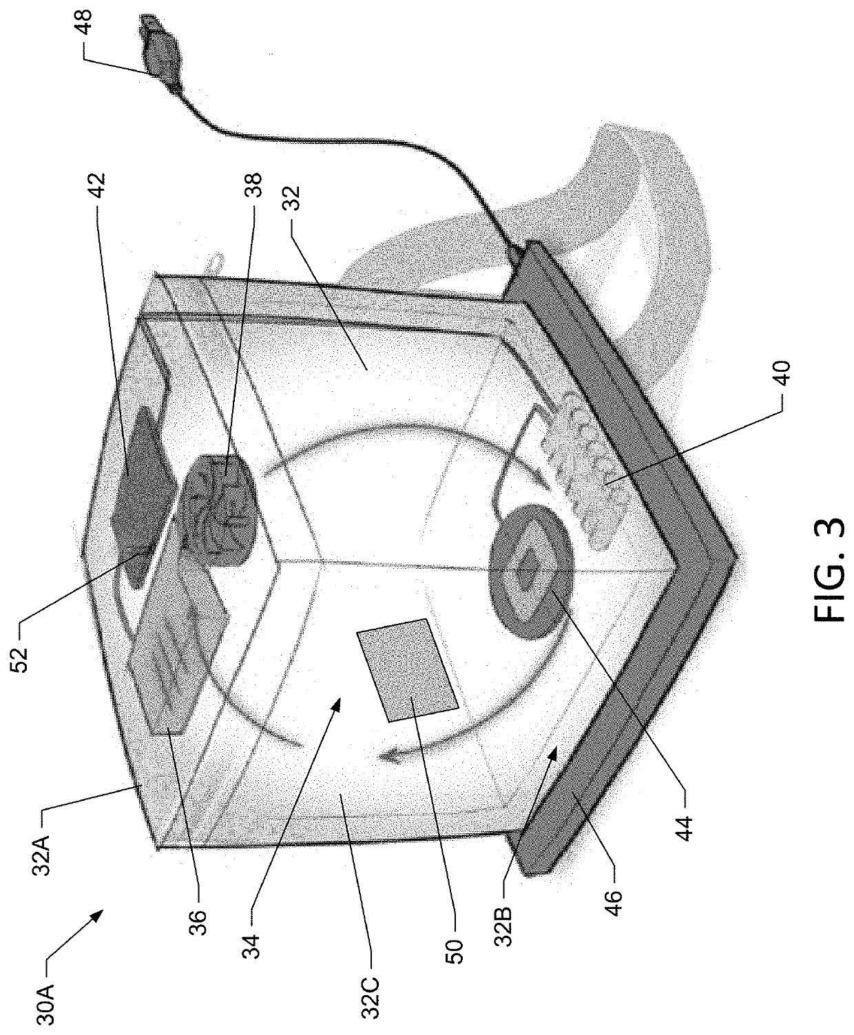
A food delivery container including a plurality of insulated walls that form a food chamber, and a climate control system. The climate control system includes an air flow pathway and a heating and/or cooling element positioned within the air flow pathway. A fan is in air flow communication with the food chamber through a first inlet opening and a first outlet opening in the one of the plurality of insulated walls. The fan is configured to draw in air from the food chamber through the first inlet opening and push air into the food chamber through the first outlet opening such that air travels through the air flow pathway and over the cooling and/or heating element to circulate heated/cooled air within the food delivery container. The climate control system also includes a power supply configured to supply electrical power to the fan and the cooling/heating element.

Description


Claims


Application Information

Patent Timeline
Owner GPCP IP HLDG LLC
Learn More