Filter for liquid or viscous product and spraying installation including such a filter

a technology for liquid or viscous products and filters, applied in the direction of filtration separation, separation processes, mechanical equipment, etc., can solve the problems of high price, complex filter production, risk of pollution, etc., and achieve the effect of cost-effectiveness and ensuring continuity of servi

Active Publication Date: 2020-08-06
EXCEL IND INC
View PDF0 Cites 0 Cited by
  • Summary
  • Abstract
  • Description
  • Claims
  • Application Information

AI Technical Summary

Benefits of technology

[0007]Owing to the invention, changing the filtering element is simple and cost-effective. The filter involves a limited number of parts, which also makes the manipulations to change filtering elements economically advantageous. The valve is able to switch from one position to the other, thus modifying the path traveled by the liquid or viscous product. The liquid or viscous product is filtered by the filtering element inside the bucket when the valve is in its first position. The second position of the valve serves to create a bypass circuit, making it possible to isolate the receiving volume with respect to the tubings, without creating too many or excessively large retention zones, which makes it possible to disassemble the bucket and access the filtering element to replace it, without stopping the installation. The continuity of service is thus ensured.

Problems solved by technology

The major drawbacks are in particular the high price, for example in the case of a bypass circuit using two filter bodies and four valves, or the risk of pollution, for example the case of a bypass circuit with no filter body, using a simple pipe where the liquid or viscous product can deteriorate between two uses.
This filter is complex to produce and includes many liquid retention areas.

Method used


Image

  • Filter for liquid or viscous product and spraying installation including such a filter
  • Filter for liquid or viscous product and spraying installation including such a filter
  • Filter for liquid or viscous product and spraying installation including such a filter

Examples


Embodiment Construction

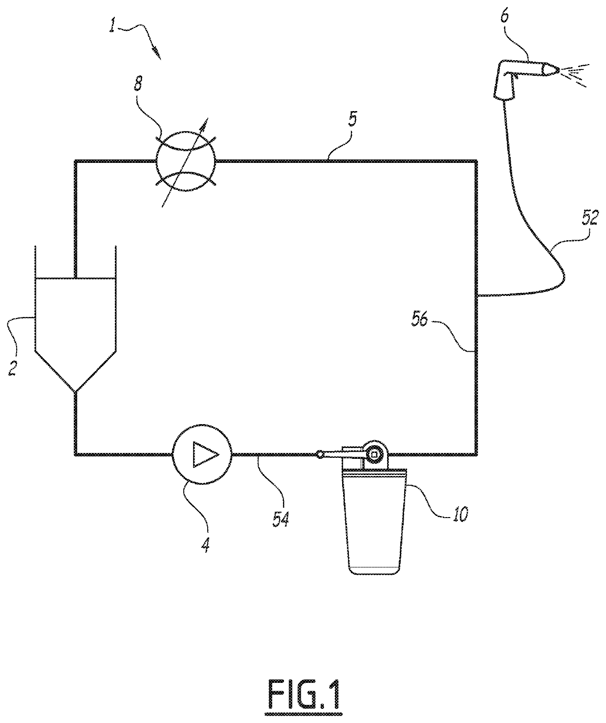
[0027]FIG. 1 shows an installation 1 for spraying liquid product including a tank 2 of liquid product, a pump 4 and a sprayer 6. In practice, installation 1 may include several other sprayers, which are not shown, for clarity of the drawing. Optionally, installation 1 also includes a pressure regulator 8. Tank 2, pump 4, sprayer 6 and, if applicable, pressure regulator 8 are coupled by an assembly 5 of pipes suitable for conveying the liquid product between the components of the installation.

[0028]The liquid product is for example a coating product, such as paint or varnish.

[0029]Sprayer 6 may be of the pneumatic or “airless” type, and may or may not be electrostatic. It may be a manual gun, as shown in FIG. 1, or in a variant, an automatic sprayer, known in itself.

[0030]Installation 1 additionally includes a filter 10 for a liquid product, as disclosed hereinafter. This filter is intercalated, in assembly of pipes 5, between tank 2 and a tapping 52 of assembly 5 dedicated to the su...


PUM

PropertyMeasurementUnit
angleaaaaaaaaaa
viscousaaaaaaaaaa
volumeaaaaaaaaaa

Abstract

A filter for a liquid for viscous product including a filtering element and a bucket defining a receiving volume accommodating the filtering element, the filter including a liquid or viscous product intake tubing and a liquid or viscous product discharge tubing, the filter including a valve configured to assume a first position, where the valve couples the intake tubing to the receiving volume and this receiving volume to the discharge tubing, and a second position, where the valve couples the intake tubing to the discharge tubing and isolates the receiving volume relative to the two tubings.

Description

CROSS-REFERENCE TO RELATED APPLICATION[0001]This application claims priority of French Patent Application No. 19 00962, filed on Jan. 31, 2019.FIELD OF THE INVENTION[0002]The present invention relates to a filter for a liquid or viscous product. This filter comprises a filtering element and a bucket defining a receiving volume accommodating the filtering element, as well as an intake tubing and a discharge tubing for the liquid or viscous product.BACKGROUND OF THE INVENTION[0003]In the field of installations including distribution circuits for liquid or viscous products comprising filters, a bypass circuit can be placed in order to ensure the service continuity of an installation during a change of filtering element. Several methods of changing a filtering element are known; each method has advantages and drawbacks. The major drawbacks are in particular the high price, for example in the case of a bypass circuit using two filter bodies and four valves, or the risk of pollution, for ...

Claims


Application Information

Patent Timeline
Patent Type & Authority Applications(United States)
IPC IPC(8): B01D35/147B01D35/02B01D29/11B05B15/40
CPCB01D29/114B01D2201/4061B05B15/40B01D35/147B01D35/02B01D29/33F16K11/085F16K11/0876B01D29/15B01D36/001B01D35/1573B01D35/306F16K11/0856F16K11/0873
Inventor BATLLO, BENOÎT
Owner EXCEL IND INC
Why Eureka
Try Eureka