System and method for providing a conduit sealingly to a through-opening in a plate-shaped construction element

Pending Publication Date: 2020-08-06
BEELE ENG
0 Cites 0 Cited by

AI-Extracted Technical Summary

Problems solved by technology

Welding requires skilled workers which are accordingly well-paid and thus costly.
As these workers are during welding exposed to hazardous and relatively unhealthy conditions, welders are nowadays highly paid.
In the world there is a shortage of good welders.
Also this drives up the price for getting a welding job done.
Not only does welding drive up the price of a construction, welding inherently changes locally the structure of the metal plate-shaped construction element, often introducing a weakness in ...

Abstract

System for providing a conduit sealingly to a through-opening in a plate-shaped construction element so that at least one pipe and/or cable can extend through the conduit and so that after sealing remaining space in the conduit a completely sealed-off pipe and/or cable penetration through the plate-shaped construction element is obtained, wherein the system is such that it is mechanically mountable, wherein the system is further such that it is mountable from only one side of the plate-shaped construction element, by only one worker.

Application Domain

Branching pipesCable inlet sealing means

Technology Topic

PhysicsStructural engineering +4

Image

  • System and method for providing a conduit sealingly to a through-opening in a plate-shaped construction element
  • System and method for providing a conduit sealingly to a through-opening in a plate-shaped construction element
  • System and method for providing a conduit sealingly to a through-opening in a plate-shaped construction element

Examples

  • Experimental program(1)

Example

[0023]In the drawing, like parts are referred to by like references.
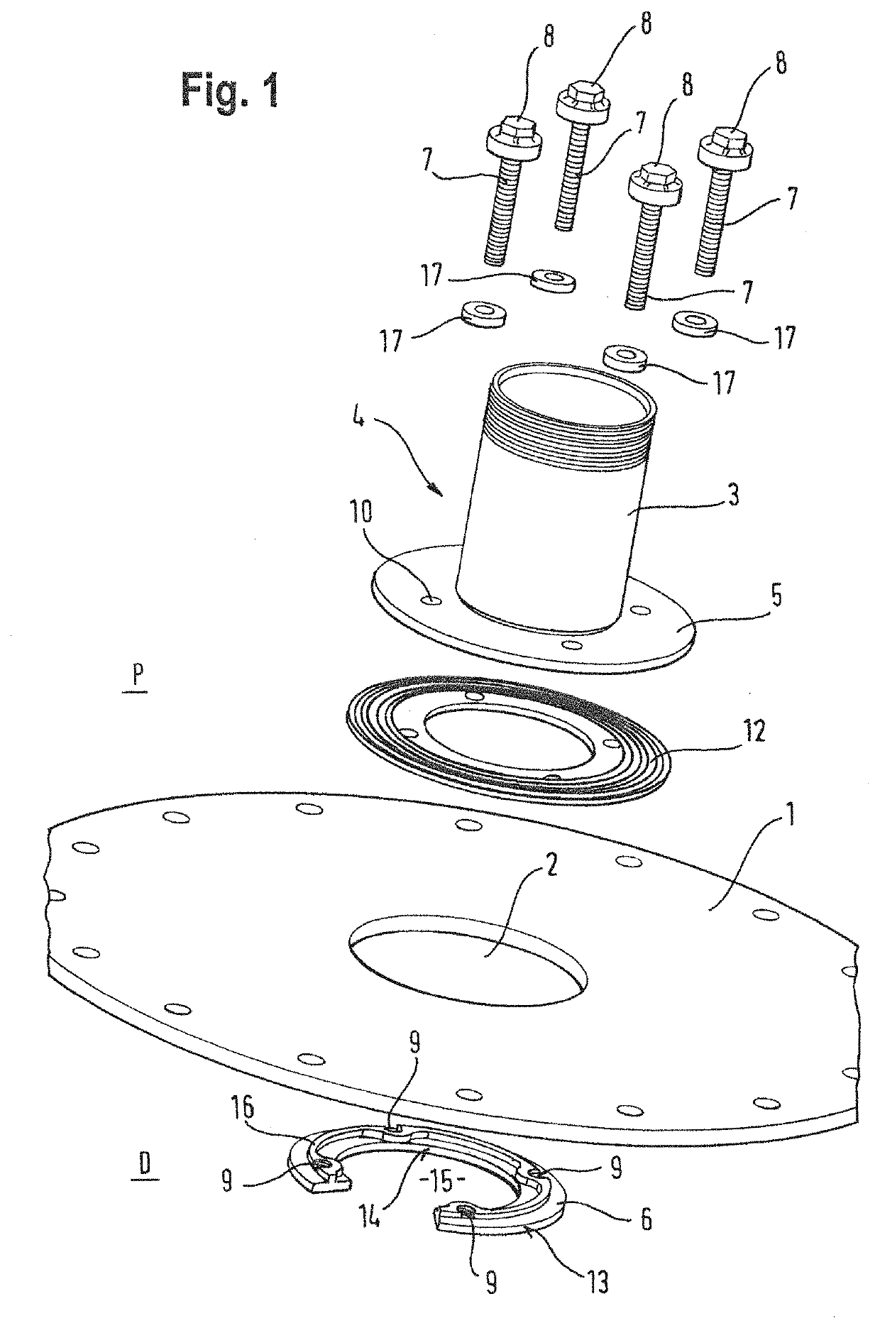
[0024]FIG. 1 shows a plate-shaped construction element 1 having a through-opening 2. For the purpose of clarity, the plate-shaped construction element 1 is shown to be a circular element. However, in practice such a plate-shaped construction element is often a part of a wall in a metal construction such as a vessel or an oil platform. The plate-shaped construction element may have any further shape and be any part of a construction. FIG. 1 shows a conduit 3. Apart from the plate-shaped construction element 1, the parts shown in FIG. 1 are each part of an example of a system for providing a conduit sealingly to the through-opening 2 in the plate-shaped construction element 1, so that at least one pipe and/or cable can extend through the conduit 3 and so that after sealing the remaining space in the conduit 3 a completely sealed-off pipe and/or cable penetration through the plate-shaped construction element 1 can be obtained. As noticeable in FIG. 1, the system is such that it is mechanically mountable. Without further explanation it is perhaps not noticeable from FIG. 1 that the system is further such that it is mountable from only one side of the plate-shaped construction element. A further explanation on this point will follow below. It may equally not be noticeable from FIG. 1 that the system is mountable by only one worker, who is operating from a proximal side of the plate-shaped construction element 1. Throughout the present disclosure, the proximal side P will be the side from which the single worker will be operating when mounting the conduit 3 to the through-opening 2. The distal side is the other side of the plate-shaped construction element.
[0025]The system comprises a conduit part 4 having the conduit 3 for extending from and/or through the through-opening 2 and having outside the conduit 3 a circumferentially extending member 5 for placement at the proximal side P of the plate-shaped construction element 1 parallel to a circumference of the through-opening 2. Most of the circumferentially extending members will simply be a flange 5 that is connected to conduit 3, as shown in FIG. 1. The system further comprises an anchor part 6 for placement at a distal side D of the plate-shaped construction element at a number of positions along a circumference of the through-opening 2. The system further comprises at least one connecting element 7 for connecting the circumferentially extending member 5 of the conduit part 4 with the anchor part 6. In most examples, the connecting parts will be bolts, having threads, and will have a head 8 for coupling to a tool that can swiftly rotate a connecting element 7 around its axis. The threaded end of the bolt is ideally connected to through-hole 9 that is equally threaded and in the anchor-part 6. That connecting element then preferably equally extends through through-holes in gasket 17, and flange 10 and through a through-hole in sealing gasket 12. That one of the connecting elements 7 for connecting the circumferentially extending member 5 of the conduit part 4 with the anchor part 6 allows for placement of the anchor part 6 at the distal side D of the plate-shaped construction element 1 at a number of positions along a circumference of the through-opening 2 whilst being connected to the conduit part 4. For visualizing this, the reader is referred to image A, B and C in FIG. 6. Image A and B show that the anchor part 6 is connected by connecting element 7 to conduit part 4. In image C it is shown that the connecting element 7 already shown in image D already connects anchor part 6 while that anchor part 6 is placed at the distal side D of the plate-shaped construction element 1. Other connecting elements 7, each here referred to as connecting element 7′, are during the time that the anchor part 6 is placed at the distal side D of plate-shaped construction element 1 are at that moment in time not yet connecting circumferentially extending member 5 and anchor part 6. Clearly, each of the at least one connection elements 7, 7′ is suitable for bringing the conduit part 4 at the proximal side P of the plate-shaped construction element 1 parallel to a circumference of the through-opening 2 whilst bringing or keeping the anchor part 6 at the number of positions along a circumference of the through-opening 2 at the distal side D of the plate-shaped construction element 1. As a result thereof the plate-shaped construction element 1 can be “clamped in” by the conduit part 4 and the anchor part 6. In practice, this “clamping-in” of the plate-shaped construction element occurs by rotating each of the connecting elements (in this example each bolt) around its axis 7, 7′. The sequence of events as shown in FIG. 6, particularly image A, B and C is that first one connecting element 7 is put through a through-hole in circumferentially extending member 5, put through a through-hole in a sealing gasket 11, and then put in a through-hole 9 of anchor part 6. (It is assumed that sealing gasket 17 had already been placed in a seat in head 8). Then, as shown in image B of FIG. 6, whilst being connected, anchor part 6 is put through the through-opening 2 and placed at the distal side D of the plate-shaped construction element 1. Then the other connecting elements 7′ are equally inserted in through-holes 10, 12 and 9 (which are then put in alignment relative to each other) and the conduit part 4 and anchor part 6 are brought together by rotating each of connecting elements 7, 7′ around its axis. It is possible that only one connecting element at the time is being rotated. The entire mounting of the conduit 3 to the through-opening 2 can be done from only one side of the plate-shaped construction element 1. It is further clear that the mounting can be done by only one worker, who is operating from the proximal side P.
[0026]Anchor part 6 is suitable for being put from the proximal side P of the plate-shaped construction element 1 through the through-opening 2, at the distal side D of the plate-shaped construction element 1. In the example shown, anchor part 6 is C-shaped or U-shaped. It is equally possible that anchor part 6 can adopt a C- or U-shape.
[0027]For further assisting visualization of the conduit as provided sealingly to the through-opening 2, reference is made to FIGS. 2, 3 and 4.
[0028]We now turn to preferred features of anchor part 6. Preferably anchor part 6 has an outer contour 13 defined by the most outer dimensions of the anchor part 6. Anchor part 6 preferably also has an inner contour 14 defining free space 15. The anchor part 6 has between the outer contour 13 and the inner contour 14, and preferably closer to the inner contour, 14 at least one connecting part 9 for connecting via at least one of the connecting elements 7 with a part of the conduit part 4 that is outside the inner circumference of the conduit 3. Ideally, this is such that in a mounted condition of the system the conduit 3 can be in the free space 15 of the anchor part 6 or such that in a mounted condition of the system an imaginary extension of the conduit 3 in an axial direction thereof can be in the free space 15 of the anchor part 6.
[0029]The anchor part 6 is preferably provided with a fixator for at least temporarily fixating the anchor part 6 against the distal side D of the plate-shaped construction element 1 at a number of positions along a circumference of the through-opening 2, optionally before connecting the anchor part 6 and the conduit part 4. The number of positions may be limited to one. The fixator may be self-clamping into the through-opening 2. The fixator may also comprise at least one lip 16 which may preferably be hook-shaped so as to allow the anchor part 6 to hang on a rim of the through-opening 2. Alternatively, or additionally, the fixator may comprise an adhesive tape, or a glue. It is preferable that the fixator comprises a lip 16, as this allows for some movement along the circumference of the through-opening 2 whilst the conduit part 4 and the anchor part 6 are brought together to “clamp-in” the plate-shaped construction element 1. However, the present disclosure envisages that such a fixation is not necessary in view of the one connecting element 7 that connects the anchor-part and the conduit part whilst putting the anchor-part through the through-opening at the distal side of the plate-shaped construction element.
[0030]Preferably, the anchor part 6 is such that it can be positioned at the distal side D of the plate-shaped construction element 1 in a stable position relative to the plate-shaped construction element, such that it is connectable or connected to the conduit part 4 when that conduit part 4 is positioned at the proximal side P of the plate-shaped construction element 1 parallel to a circumference of the through-opening 2. Thus, optionally, anchor part 6 is first put through the through-opening 2 and then positioned such that it is stable and can be connected to the conduit part 4. Alternatively, and preferably, anchor part 6 and conduit part 4 are connected before putting anchor part 6 through the through-opening 2 for placement at the distal side D parallel to a circumference of the through-opening 2. Connecting before putting through the through opening has the advantage that the anchor-part cannot fall down at the distal side D.
[0031]It has turned out to be unnecessary to provide for dedicated means for blocking rotation of the anchor-part when only one connecting element is rotated for bringing the anchor-part and the conduit part together after initial placement at the respective sides of the plate-shaped construction element. As soon as the anchor-part is somewhat firmly placed against the plate-shaped construction element, no rotation of the anchor-part will take place, allowing for advancing the connecting element such that the distance between the anchor-part and the conduit-part reduces. A handy worker can easily mount the system on his/her own. On the other hand, it remains possible to apply a rotation blocker. The anchor-part itself is not necessarily put at the distal side in a sealing fashion, as sealing can be established up to completion at the proximal side.
[0032]Further, examples of a system of the present disclosure are such that these are mountable without having to provide in addition to the through-opening further through-openings through the plate-shaped construction element. Put simply, this is possible when the bolts extend through the through-opening 2 in the plate-shaped construction element, so that no special through-holes need to be provided in the plate-shaped construction element 1.
[0033]Attention is now given to features that allow for providing the conduit 3 to the through-opening 2 sealingly. For that purpose the circumferentially extending member 5 of the conduit part 4 comprises a first seat for a sealing gasket 12 for positioning between the plate-shaped construction element and the conduit part 4. In the examples discussed, the seat comprises an annular-shaped cavity in the circumferentially extending member 5 for hosting this sealing gasket. The thickness of the sealing gasket 12 is such that no matter how tight the conduit part 4 and the anchor part 6 clamped in plate-shaped construction element 1, conduit part 4, or in any case the circumferentially extending member 5 thereof, will not be touching plate-shaped construction element 1.
[0034]Each of the at least one connecting elements 7 have in their heads a second seat for a second sealing gasket 17. Ideally, in use this head is at a side that will remain in use at a proximal side P of the plate-shaped construction element 1. Then the second sealing gasket 17 can be positioned against the circumferentially extending member 5 when the conduit part 4 and the anchor part 6 are brought together for “clamping in” the plate-shaped construction element 1. The second seat preferably comprises an annular-shaped cavity for hosting the sealing gasket 17. The thickness of the sealing gasket 17, in relation to the shape and dimensions of the second seat, are such that the seat does not touch the circumferentially extending member 5 of the conduit part 4, not even when the conduit part 4 and anchor part 6 tightly clamp in plate-shaped construction element 1.
[0035]As explained above, a method for providing a conduit sealingly to a through-opening 2 in a plate-shaped construction element 1 can be such that it comprises mounting from only one side of the plate-shaped construction element 1. However, if so desired, as shown in FIGS. 2, 3 and 4, the threaded ends of the bolts sticking out on the distal side D can of course be provided with a capped nut (not shown) or any other device that further secures the conduit as mounted and that prevents people from being injured by those ends when getting too close and accidentally hitting those ends of the bolts. This however is not a necessary part of the mounting itself and can be done afterwards.
[0036]As can be seen in particular in FIG. 3, the disclosure provides a conduit assembly that has mechanically been mounted to a through-opening 2 in a plate-shaped construction element 1 without having had to provide in addition to the through-opening 2 further through-openings through the plate-shaped construction element 1.
[0037]Although so far the present disclosure referred predominantly to conduits having a circular cross section, the technical concept of the disclosure, as captured by the appended claims, also allows for application with conduits having non-circular cross sections. Thus, the conduit may be elliptical, rectangular, having rounded edges, or have any other shape. In those situations, the anchor part 6 can probably always be closed in itself and still be put from the proximal side of the plate-shaped construction element 1, through the through-opening 2, to the distal side D. In those circumstances the anchor-part 6 can abut at the entire circumference of the though-opening 2 the plate-shaped element 1. Only where the conduit has a circular cross-section, it may be necessary to have a C- or U-shaped anchor part 6. As indicated, it may also be possible to have an anchor part 6 that can adopt a C- or U-shape. For instance, the anchor part 6 may be composed of segments of a circle which are connected by means of hingeable connections, so that some of the segments can be moved radially inwardly and thus so that the anchor part 6 overall adopts temporarily a C- or U-shape. In that condition the anchor part can be put through the circular through-opening 2.
Y
[0038]In the example as discussed, it is the number of the connecting elements and the length of each thereof that allows for the mounting by a single worker from only one side. It requires a bit of training to straightforwardly mount the system. However, a handy worker can for sure, after some training, routinely mount the system, even in circumstances where little light is available. In other words, with just the availability of a battery holding electrical driver for rotating the connecting elements, it is possible to use the system and successfully mount it, without having electrical wires around. No other parts or tools are required. Instead of 4 connecting elements, it is also possible to use only 2 connecting elements, or to use 5 or 6 and even more, depending on the diameter of the conduit. Indeed, many other examples are possible within the framework of the claims as appended.

PUM

no PUM

Description & Claims & Application Information

We can also present the details of the Description, Claims and Application information to help users get a comprehensive understanding of the technical details of the patent, such as background art, summary of invention, brief description of drawings, description of embodiments, and other original content. On the other hand, users can also determine the specific scope of protection of the technology through the list of claims; as well as understand the changes in the life cycle of the technology with the presentation of the patent timeline. Login to view more.
Why Eureka
Try Eureka