
Tyre

a technology of tyres and sidewalls, applied in the field of tyres, can solve the problems of noise performance degradation, ride comfort degradation, etc., and achieve the effects of high stiffness, high stiffness, and high stiffness

Active Publication Date: 2020-08-13
SUMITOMO RUBBER IND LTD
View PDF6 Cites 0 Cited by
  • Summary
  • Abstract
  • Description
  • Claims
  • Application Information

AI Technical Summary

Benefits of technology

The present invention aims to improve the steering stability, ride comfort, and noise performance of a pneumatic tyre by improving the arrangement of lateral grooves in the tread portion of the tyre. The invention addresses the problem of high stiffness in the tread center land portion, which causes vibration and impact noise during grounding. The solution involves designing the lateral grooves in a specific way to reduce the stiffness of the tread center land portion, thereby improving the overall performance of the tyre.

Problems solved by technology

In the above-mentioned pneumatic tyre, since the tread center land portion has high stiffness, vibration of the tread portion tends to be transmitted to a vehicle body, resulting in degradation in ride comfort.
In addition, the tread center land portion with high stiffness tends to generate large impact noise upon grounding, leading to deterioration in noise performance.

Method used


Image

  • Tyre
  • Tyre
  • Tyre

Examples


example-1

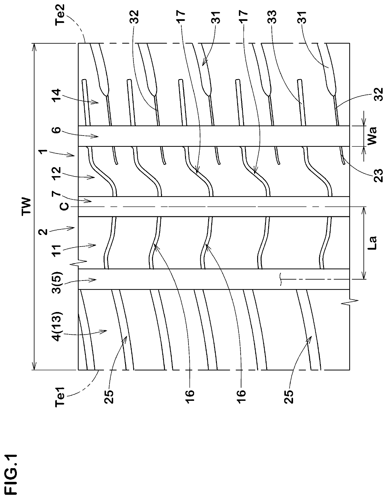
[0097]Tyres (205 / 55R16) having the basic tread pattern shown in FIG. 1 were manufactured by way of trial based on the detail shown in Table 1. As a comparative example 1 (Ref. 1), as shown in FIG. 9, tyres which includes the first middle land portion (a) and the second middle land portion (b) provided with straight lateral grooves (c) having the same circumferential length of the groove-reference-straight-lines were also manufactured. Note that the tread pattern of comparative example 1 is substantially the same as the tread pattern shown in FIG. 1 except the above-mentioned structure. Then, steering stability, ride comfort and noise performance of each test tyre was tested. The common specification and the test method are as follows:

[0098]rim size: 16×6.5J;

[0099]tyre inner pressure: front 200 kPa and rear 200 kPa;

[0100]test vehicle: FF vehicle having displacement of 1600 cc; and

[0101]tyre location: all wheels.

Steering stability test:

[0102]A test driver drove the above-mentioned tes...

example-2

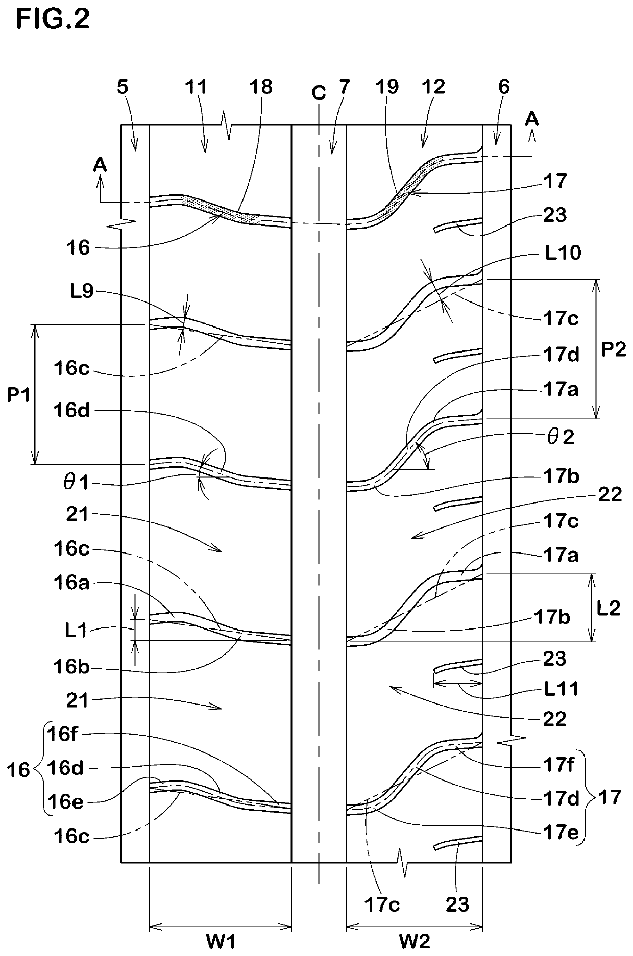
[0107]Tyres (205 / 55R16) having the basic tread pattern shown in FIG. 1 were manufactured by way of trial based on the detail shown in Table 2. As a comparative example 2 (Ref. 2), as shown in FIG. 10, tyres which includes the first middle land portion (d) and the second middle land portion (e) provided with curved grooves (f) having the center portions having the same angle were also manufactured. Note that the tread pattern of comparative example 2 is substantially the same as the tread pattern shown in FIG. 1 except the above-mentioned structure. Then, steering stability and noise performance of each test tyre was tested. The common specification and the test method are the same as mentioned above. As to the test results, the score as well as the index is indicated based on Ref. 2 being 100.

[0108]Table 2 shows the test results.

TABLE 2Ref. 2Ex. 10Ex. 11Ex. 12Ex. 13Ex. 14Ex. 15Ex. 16Ex. 17Ex. 18Figure showing first and secondFIG.FIG. 2FIG. 2FIG. 2FIG. 2FIG. 2FIG. 2FIG. 2FIG. 2FIG. 2...

example-3

[0110]Tyres (205 / 55R16) having the basic tread pattern shown in FIG. 1 were manufactured by way of trial based on the detail shown in Table 3. As a comparative example 3 (Ref. 3), as shown in FIG. 11, tyres which includes the second shoulder land portion (g) provided with lateral grooves (h) traversing completely in the tyre axial direction were also manufactured. Further, the tread portion of comparative example 3 is not provided with any connecting sipes but provided with non-traversing narrow grooves which are the same as the non-traversing narrow grooves shown in FIG. 1. Note that the tread pattern of comparative example 3 is substantially the same as the tread pattern shown in FIG. 1 except the above-mentioned structure. Then, steering stability and noise performance of each test tyre was tested. The common specification and the test method are the same as mentioned above. As to the test results, the score as well as the index is indicated based on Ref. 3 being 100.

[0111]Table ...


PUM


Abstract

A tyre includes a tread portion including first and second land portions. The first middle land portion is provided with first middle lateral grooves traversing the first middle land portion completely. The second middle land portion is provided with second middle lateral grooves traversing the second middle land portion completely. Each of the first middle lateral grooves and the second middle lateral grooves is a curved groove which includes a first convex portion located on a first side with respect to a groove-reference-straight-line that connects both ends of a groove centerline of the curved groove and a second convex portion located on a second side with respect to the groove-reference-straight-line, and a circumferential length of the groove-reference-straight-line of each first middle lateral groove is smaller than a circumferential length of the groove-reference-straight-line of each second middle lateral groove.

Description

BACKGOUND ARTField of the Disclosure[0001]The present disclosure relates to a tyre, more particularly to a tyre including a tread portion having a designated mounting direction to a vehicle.Description of the Related Art[0002]Recently, tyres having tread portions with a designated mounting direction to a vehicle have been proposed. For example, the following Patent document 1 discloses a pneumatic tyre including a tread center land portion which is provided with a plurality of center sipes having a width of less than 2 mm, but is not provided with any grooves that have groove widths more than 2 mm and that traverse the land portion completely in the tyre axial direction. The above-mentioned pneumatic tyre enhances stiffness of the tread center land portion, thus expecting to improve steering stability on dry road conditions.[Patent document 1] Japanese Unexamined Patent Application Publication 2015-140047SUMMARY OF THE DISCLOSURE[0003]In the above-mentioned pneumatic tyre, since the...

Claims


Application Information

Patent Timeline
Patent Type & Authority Applications(United States)
IPC IPC(8): B60C11/03B60C11/12B60C13/00
CPCB60C13/001B60C2011/0358B60C2011/0313B60C11/0302B60C11/12B60C2011/0374B60C11/0311B60C2011/0344B60C11/1204B60C11/1259B60C11/1272B60C11/13B60C11/0304B60C11/0306B60C2011/0369B60C11/1369
Inventor OSAWA, TAKUYANISHIJIMA, SHIGEKISUNAZUKA, DAI
Owner SUMITOMO RUBBER IND LTD
Learn More