Vibration Dampening Muzzle Device for a Small Arms Weapon

a small arms and muzzle technology, applied in the direction of muzzle attachment, etc., can solve the problems of affecting the eyesight of the shooter and others, the effect of reducing the range of motion of the muzzle, and the effect of reducing the range of motion

Inactive Publication Date: 2020-08-20
CALDERWOOD RICHARD +1
View PDF0 Cites 17 Cited by
  • Summary
  • Abstract
  • Description
  • Claims
  • Application Information

AI Technical Summary

Problems solved by technology

Muzzle flash is undesirable in that it may, in low light shooting situations, have an adverse effect on the eyesight of the shooter and others nearby, by causing their pupils to contract.
Muzzle flash is even more undesirable in combat, as it gives away the location of the shooter, who can then be targeted by the enemy.
When a weapon is fired, vibrations are induced in the material, typically steel, of its barrel.
All are believed to cause ballistic inaccuracies by virtue of movements they induce in the material of the barrel, particularly at the muzzle.

Method used


Image

  • Vibration Dampening Muzzle Device for a Small Arms Weapon
  • Vibration Dampening Muzzle Device for a Small Arms Weapon
  • Vibration Dampening Muzzle Device for a Small Arms Weapon

Examples


first embodiment

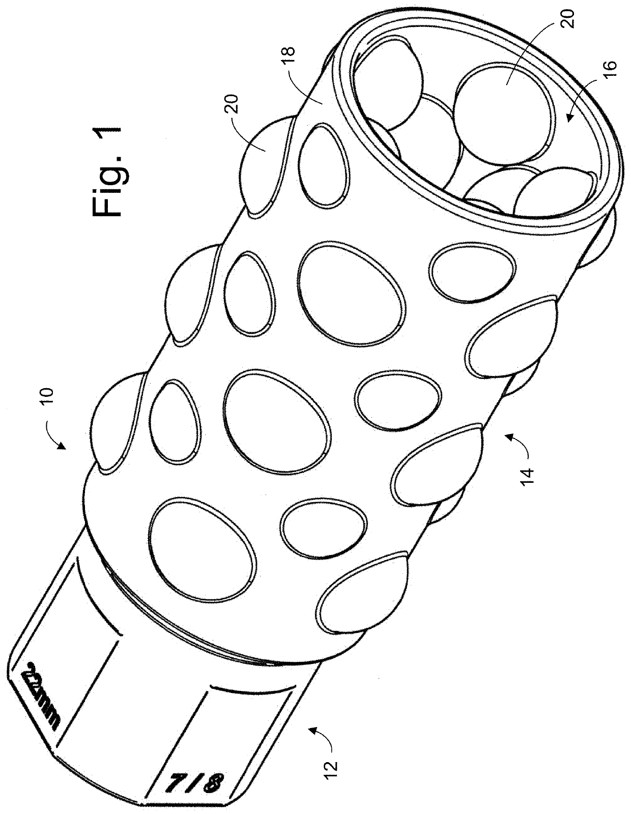
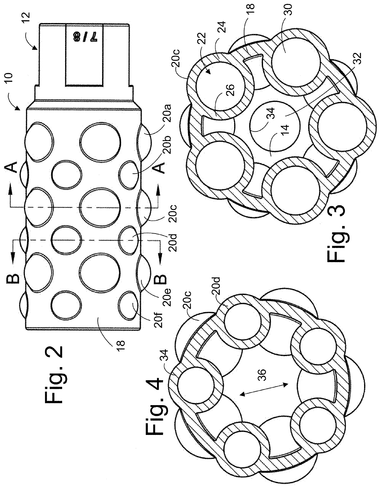
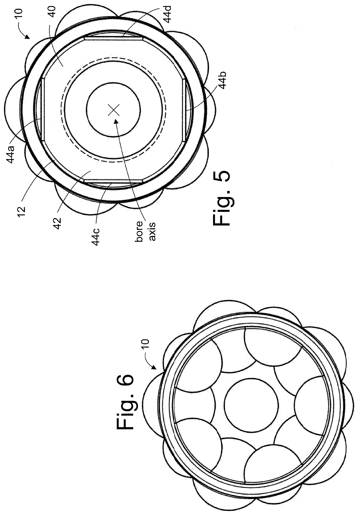
[0013]FIGS. 1-8 illustrate the invention, configured as a flash hider and having a plurality of groups of different sizes of spherical vibration dampening devices.

second embodiment

[0014]FIGS. 9-11 illustrate the invention, configured as a flash hider and having a plurality of groups of different sizes of vibration dampening devices which are elongated in a direction parallel with the bore axis, with groups of different sizes and at different spacings.

third embodiment

[0015]FIGS. 12-14 illustrate the invention, configured as a flash hider and having a plurality of annular ring-shaped vibration dampening devices.


PUM


Abstract

A muzzle device is provided comprising a cylindrical body defining a device axis. The body having a rear end with an attachment facility configured to connect to a firearm barrel muzzle and a forward end. The body defines a bore extending along the device axis, and further the body defines a plurality of enclosed voids.

Description

CROSS-REFERENCE TO RELATED APPLICATIONS[0001]This application claims the benefit of U.S. Provisional Patent Application No. 62 / 782,567 filed on Dec. 20, 2018, entitled “Vibration Dampening Muzzle Device for a Small Arms Weapon”, which is hereby incorporated by reference in its entirety for all that is taught and disclosed therein.FIELD OF THE INVENTION[0002]The present invention relates to a muzzle device for a small arms weapon, and more particularly, to a vibration dampening muzzle device.BACKGROUND OF THE INVENTION[0003]FIG. 74 illustrates the distal end portion of a barrel 1 which is used to accelerate and direct the projectile in a small arms weapon such as a rifle, shotgun, or handgun, as is known in the prior art. The exemplary barrel includes a muzzle 2, which is the opening through which the projectile(s) exit after being fired. The barrel further includes an end portion 3 which is optionally threaded in order that a muzzle device (not shown) may be affixed. The end portion...

Claims


Application Information

Patent Timeline
Patent Type & Authority Applications(United States)
IPC IPC(8): F41A21/36
CPCF41A21/34F41A21/36
Inventor CALDERWOOD, RICHARDLOGAN, STERLING
Owner CALDERWOOD RICHARD
Why Eureka
Try Eureka