Method for measuring the muzzle velocity of a projectile or the like

a technology of projectile and muzzle velocity, which is applied in the direction of measuring explosion force, force/torque/work measurement, instruments, etc., can solve the problems of affecting the accuracy of the measurement device, the need for two sensors to be arranged at a defined spacing, and the instability of the entire weapon, so as to achieve high frequency stability

Active Publication Date: 2010-11-02
OERLIKON CONTRAVES BESCHRAENKTER HAFTUNG
View PDF21 Cites 13 Cited by
  • Summary
  • Abstract
  • Description
  • Claims
  • Application Information

AI Technical Summary

Benefits of technology

[0014]In this context, the electromagnetic field must satisfy the boundary condition for a circular waveguide and the boundary condition at the projectile. It should be noted here that the circular waveguide need not necessarily have an exactly circular cross-section. Rather, it is also possible to build a profile into the wall of the waveguide in order to achieve a desired transverse electromagnetic field distribution. This can be seen in FIG. 3, where a rib structure in the muzzle brake provides for mode selection. When all boundary conditions are met, the result is a signal strength at the location z=0 (when ZK=0) that is now determined by the position z=zP of the projectile in the waveguide. The offset ZK between the transmit coupler (3.1) and the receive coupler (3.2) can be used for better mode selection if needed. In general, however, it should be the case that ZK=0, and applies only for the receive coupler that is closest to the transmit coupler (3.1). The situation depicted in FIG. 3 shows an arrangement consisting of one transmit coupler (3.1) and one receive coupler (3.2). However, as shown in FIG. 4, multiple receive couplers (4.2) can also be placed in series very close together and thus compactly toward the barrel end and ahead of the transmit coupler (4.1) in order to improve measurement accuracy. The muzzle brake is not artificially lengthened here, and thus the disadvantage of a long muzzle velocity measurement device is avoided.
[0016]The advantage of this simple measurement device is that the muzzle region or the muzzle brake need not be artificially extended. The measurement device is integrated directly into the muzzle brake. Moreover, it can be used independently of the type of ammunition (full or subcaliber). The measurement device is compact, since the barrel and the muzzle region, in particular the muzzle brake that is generally used on the gun barrel, also constitute part of the measurement setup. The accuracy of the measurement itself is independent of the oscillator frequency, so that a high degree of frequency stability for the oscillator is not required as in prior art Doppler frequency measurements. It is only necessary to avoid exceeding an upper frequency or dropping below a lower frequency. Moreover, the simple measurement results from the fact that the envelope is detected instead of the frequency. The measurement device can be used in single-mode operation.

Problems solved by technology

It is disadvantageous in this regard that two sensors must be arranged at a defined spacing.
This can lead to instability of the entire weapon or cause problems when using subcaliber ammunition.
The sabots that detach upon emergence from the gun barrel can damage the measurement device.
This has the result that mounting the sensors on or in the barrel is possible only under difficult conditions, or is even impossible.
Another disadvantage results from the fact that the measurements of the flight velocity and the programming of the detonation time outside the gun barrel by means of a microwave transmitter require a certain resistance to interference for the transmission of information between transmitter and shell.
Interference from natural sources, as well as intentional interference from a jammer, can impede the measurement of the flight speed and the subsequent programming or even make it impossible.
The maxim today is “See but remain unseen.” If the gun reveals its position by emissions, that gun is in great danger from efficient weapons systems.
Vibrations arising from firing can change the instantaneous frequency of the transmitter and increase the effort required to accurately measure the frequency shift.

Method used


Image

  • Method for measuring the muzzle velocity of a projectile or the like
  • Method for measuring the muzzle velocity of a projectile or the like
  • Method for measuring the muzzle velocity of a projectile or the like

Examples


Embodiment Construction

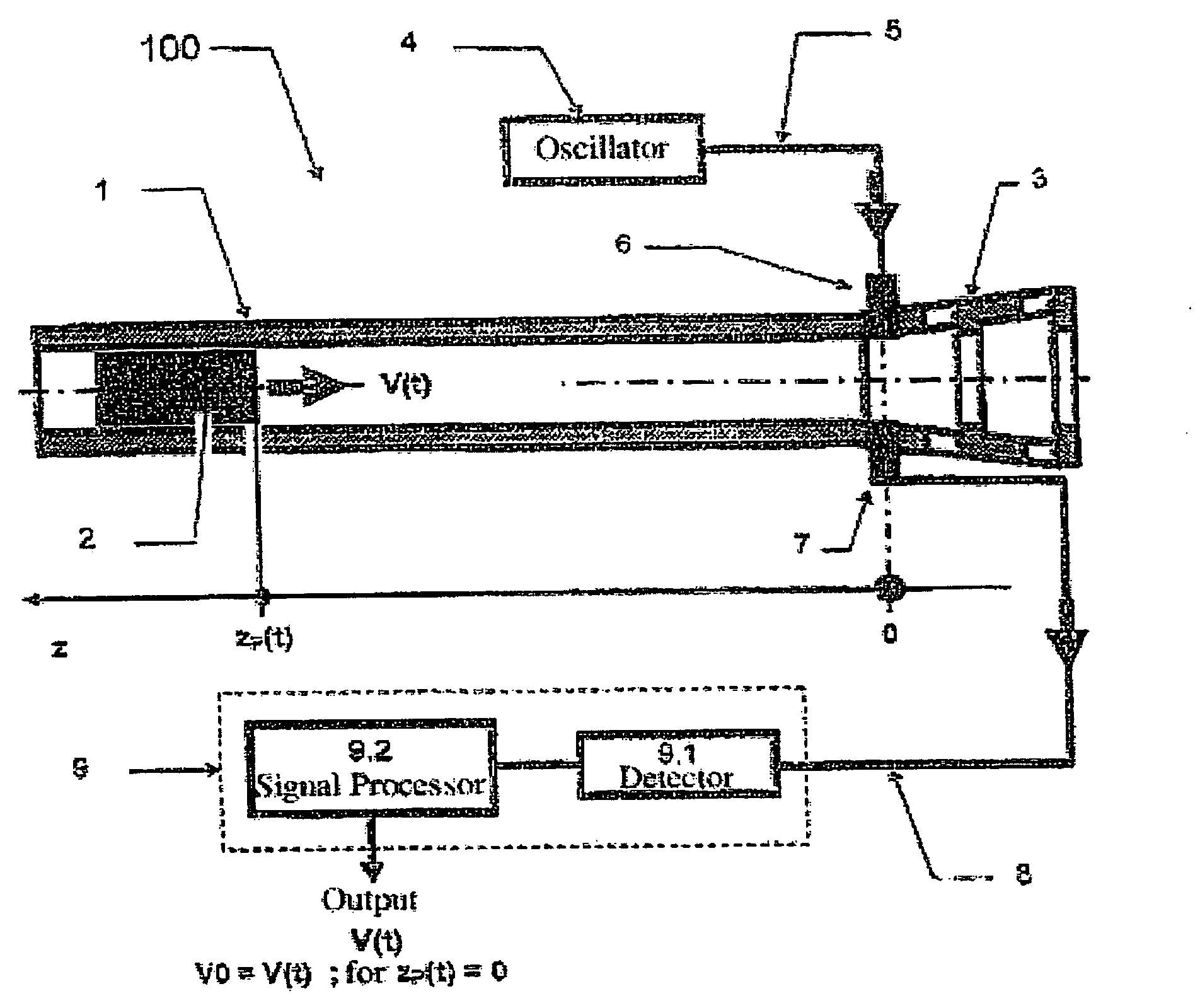
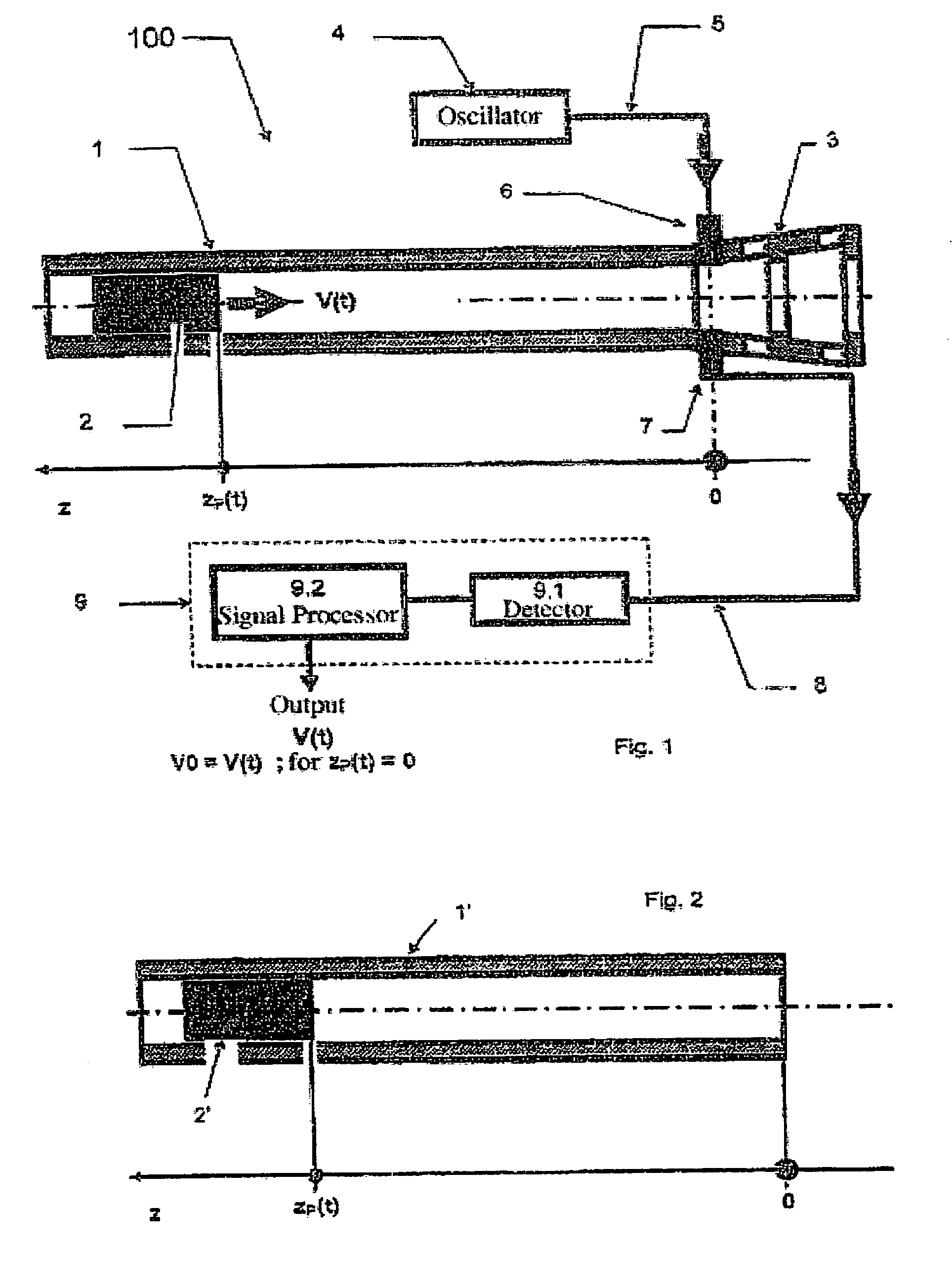
[0023]FIGS. 1 and 2 show the basic structure of a measurement device 100 for the measurement method. The measurement device 100 includes a gun barrel 1, here with a muzzle brake 3, an oscillator 4 that is electrically connected through a signal line 5 to a transmit coupler 6 for excitation. A receive coupler 7 is used for signal acquisition and is connected by a cable 8 for the received signal to the receiving unit 9, consisting of a detector 9.1 and a signal processor 9.2. The two couplers 6, 7 are integrated into the muzzle brake 3 and form a coupler pair.

[0024]The oscillator 4 here excites a waveguide mode (TE; TM) through the transmit coupler 6. In this regard, provision is made in this example embodiment that a frequency is selected that is below the cutoff frequency of the relevant waveguide mode. The desired waveguide mode is excited by mechanical and electromagnetic mode selection. The system of the “barrel”1 (FIG. 2, waveguide 1′) and the projectile 2 (FIG. 2, cylinder 2′) ...


PUM


Abstract

It is proposed to use the gun barrel or launcher tube or the muzzle brake as a waveguide, which, however, is operated at a frequency that is below the cutoff frequency of the relevant waveguide mode. The transmit coupler excites the relevant waveguide mode. An oscillator generates the signal, which is then sent to the transmit coupler. The waveguide and the projectile form a system in which the electromagnetic field at the receive coupler is influenced by the position of the projectile. The characteristic change over time of the strength of the electromagnetic field at the location of the receive coupler that results from the change in the distance between the projectile and the receive coupler is measured and used to determine the muzzle velocity.

Description

[0001]This nonprovisional application claims priority to German Patent Application No. DE 102006058375, which was filed in Germany on Dec. 8, 2006, and to U.S. Provisional Application No. 60 / 968,883, which was filed on Aug. 29, 2007, and which are both herein incorporated by reference.BACKGROUND OF THE INVENTION[0002]1. Field of the Invention[0003]The present invention relates to a method for measuring a Muzzle Velocity of a projectile or the like.[0004]2. Description of the Background Art[0005]Prior art measurement devices and methods use at least one coil pair, which as a rule is located following a muzzle brake of a weapon. The coils here are positioned at a defined distance from one another, wherein the velocity V0 is determined by the measured time the projectile requires to travel the distance defined by the coils.[0006]Such a device is known from CH 691 143 A5. In order to measure the shell velocity of a rapid-firing gun, two sensors are arranged at a distance from one anothe...

Claims


Application Information

Patent Timeline
Patent Type & Authority Patents(United States)
IPC IPC(8): G01S13/58G01P3/66G01S13/00G01P3/00
CPCF41A21/32G01S11/023G01P3/665G01S13/58F41G3/12
Inventor FRICK, HENRY
Owner OERLIKON CONTRAVES BESCHRAENKTER HAFTUNG
Why Eureka
Try Eureka