Modular ankle prosthesis and associated method

a technology for ankles and prostheses, applied in the field of orthopaedics, can solve the problems of ankle joints, problems arising in connection with replacement joints to bone and tissue, and the use of fusing does not provide the same degree of motion, so as to eliminate the need for custom implants, eliminate the need for side specific implants, and facilitate the adjustment or selection

Inactive Publication Date: 2005-12-29
DEPUY PROD INC
View PDF27 Cites 93 Cited by
  • Summary
  • Abstract
  • Description
  • Claims
  • Application Information

AI Technical Summary

Benefits of technology

[0035] The technical advantages of the present invention, further include the ability of the implant of the present invention to permit revisions to total ankle prostheses. According to another aspect of the present invention, an implant for use in ankle arthoplasty is provided including a first member in cooperation with the tibia and a second member. A bearing member is positioned between the first member and the second member. The second member includes a portion for cooperation with the calcaneus. Since the calcaneus will provide for sufficient bone support for a revision total ankle prosthesis, the present invention thus provides for the ability to provide for revision total ankle prostheses.
[0036] The technical advantages of the present invention further include the elimination of the need for right and left hand or side specific implants. For example, according to another aspect of the present invention, a total ankle prosthesis is provided having removably connectable components. The first component may be selective, rigid positioned with respect to the other component. Optionally indicia may be positioned on one or both of the first and second components so that the relative position may be easily adjusted or selected. Thus, the present invention for the elimination of the need for side specific implants.
[0037] The technical advantages of the present invention further include the ability to eliminate the need for a custom implant. For example, according to another aspect of the present invention a kit for use in an ankle athroplasty is provided. The kit may include a plurality of first members for cooperation with the tibia and a plurality of second members for cooperation with the talus. Any of the plurality of first members for cooperation with the tibia may be used with any of the second-members for cooperation with the talus. Thus the present invention can provide for a multitude of options such that the individual needs and variations in the anatomy of patients can be accomplished with the standard set of kit components thereby eliminating the need of a custom implants. Thus the present invention provides for the elimination of the need for custom implants.
[0038] The technical advantages of the present invention further include the ability to provide improved dorsiflexion and plantar flexion as well as eversion and inversion. For example, according to one aspect of the present invention, an implant for the use of total ankle arthoplasty is provided. The implant includes a first member for cooperation with the tibia and a second member including a portion for an attachment to the calcaneus.
[0039] A bearing is positioned between the first member and the second member for movable association with the first member and the second member. By providing a implant for the use in total ankle arthoplasty that includes a portion for attachment to the calcaneus, an implant can be provided that attaches to bone that is not seriously damaged during the loosening and subsidence of a primary total ankle implant. Thus, the present invention provides for a total ankle arthoplasty with improved range of motion for the patient.

Problems solved by technology

A number of problems are associated with joint replacement.
Clearly, the use of fusing does not provide the same degree of motion as a natural ankle joint.
Problems arise in connection with the replacement joint to bone and tissue.
Ankle joints pose additional problems due to the weight supported and range of motion required for walking.
Attachment of the tibia, which extends substantially vertically is difficult, as portions of the fibula may also be removed for implants.
Matching the pivot point of the joint is critical, as misalignment can lead to difficulty in walking and other motions, which may cause the patient considerable pain.
These stresses may crack or fracture ankle components of replacement joints, which absorb a substantial amount of the pressures during the aforementioned activities.
Occasionally, however, the talus of the patient may be in such a condition that the talus does not provide sufficient support for the total ankle prosthesis.
An even more common problem with currently available total arthoplasty prostheses is the use of such prosthesis in a revision total ankle arthoplasty.
The loosened components and the subsidence of the prosthesis 2 may result in bone loss and cause severe pain to the patient.
Referring now to FIG. 6, the loosening and the subsidence of prosthesis 2 may result in loss of plantar flexion.
The mere replacement of the original prosthesis with another larger component is generally is not successful in correcting the problem.
Attempts to address the revision of the total ankle arthoplasty have met with limited success.
With some very limited success, some failed primary total ankle arthoplasty prosthesis have been replaced with a revision total ankle arthoplasty.
These prostheses can be very specific expensive and provide the surgeon with only one very specific implant option in time of the surgery.
The implantation of such custom devices is often a very technically demanding procedure as instrumentation and surgical procedures are not well established.

Method used


Image

  • Modular ankle prosthesis and associated method
  • Modular ankle prosthesis and associated method
  • Modular ankle prosthesis and associated method

Examples


Embodiment Construction

[0083] Embodiments of the present invention and the advantages thereof are best understood by referring to the following descriptions and drawings, wherein like numerals are used for like and corresponding parts of the drawings.

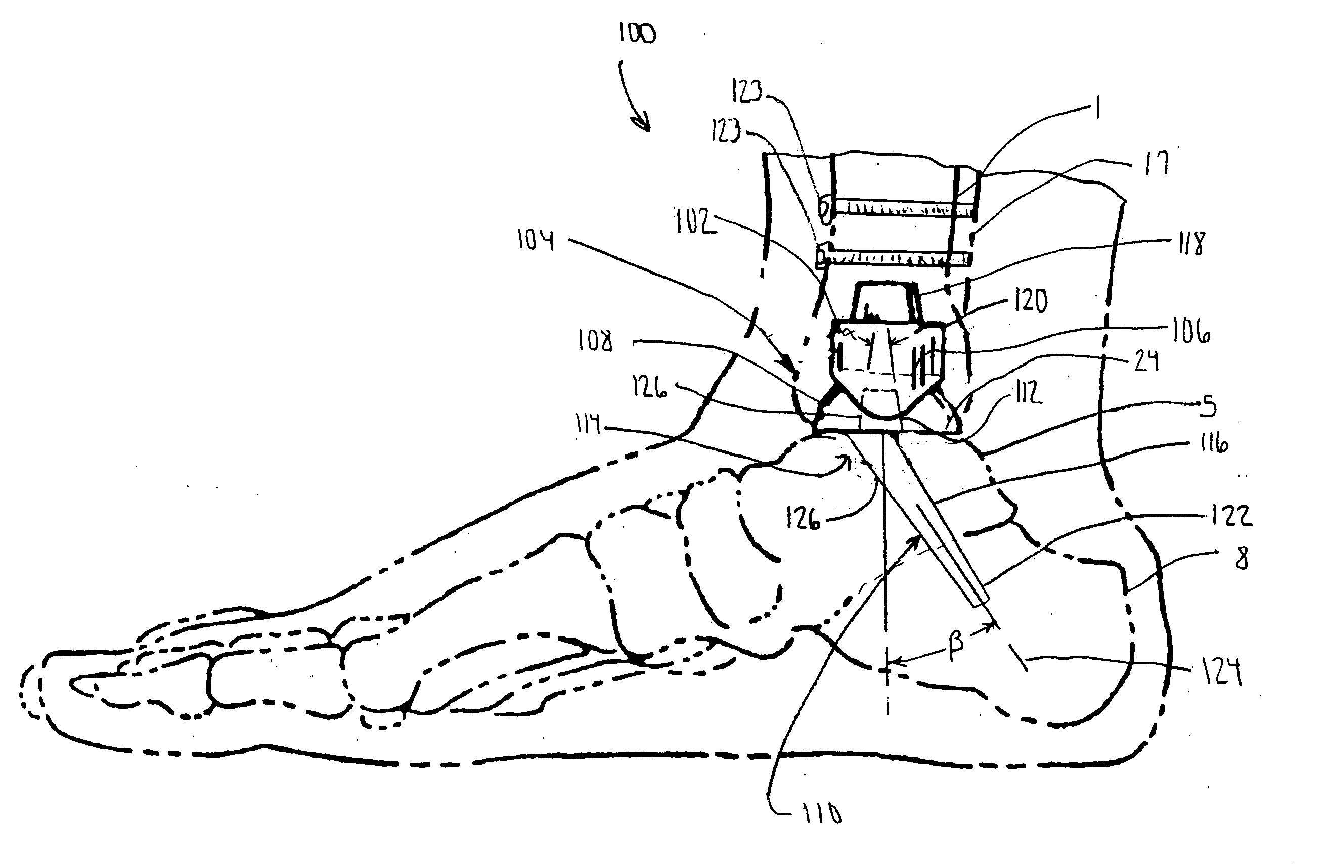
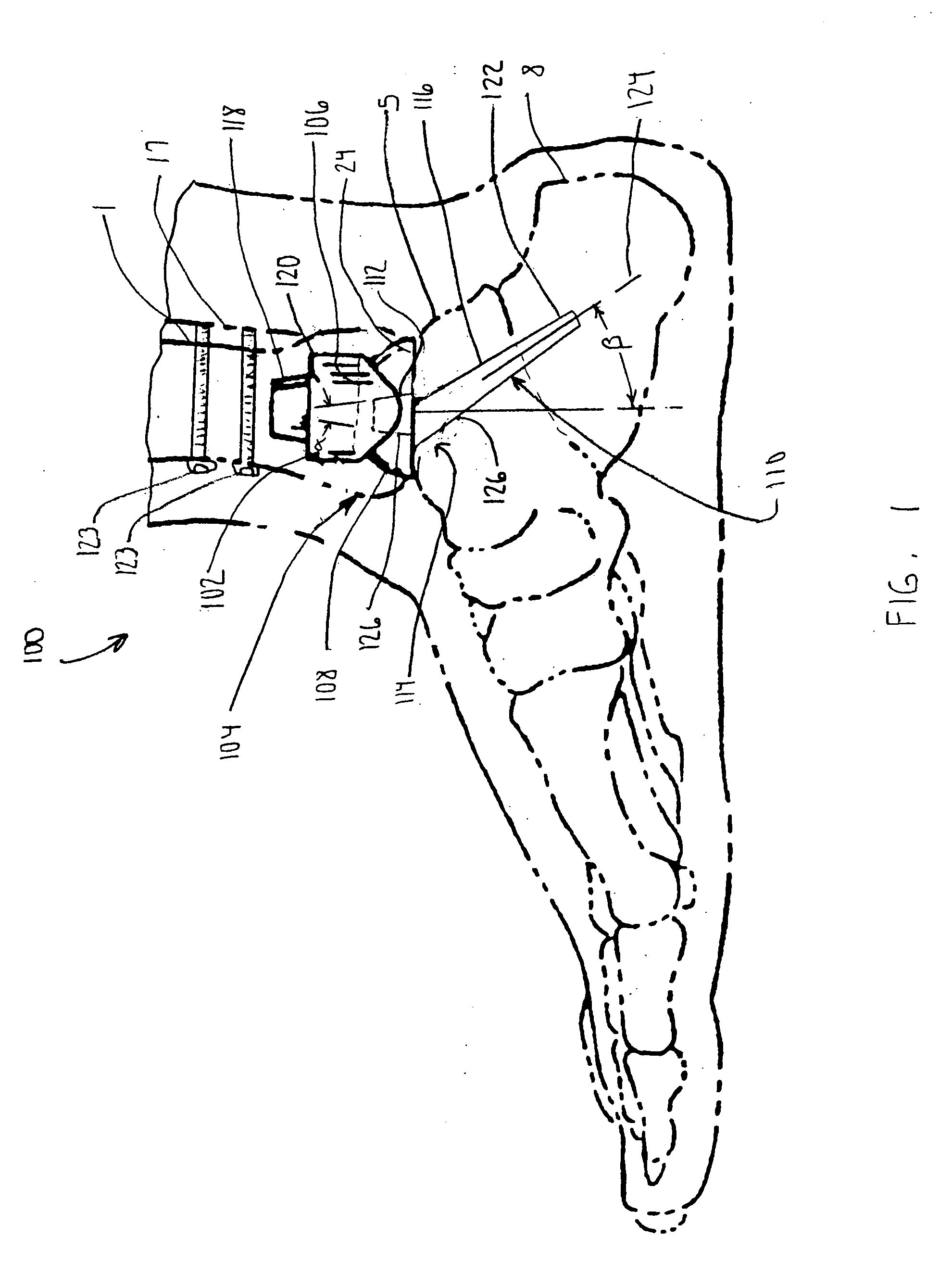
[0084] According to the present invention and referring now to FIG. 1, an implant 100 is shown in use for total ankle arthoplasty. The implant 100 includes a first member 102 for cooperation with the tibia 1. The first member 102 may also cooperate with fibula 17. It should be appreciated the tibia 1 and the fibula 17 may be secured to each other by, for example, cancellous or cortical screws 123.

[0085] Implant 100 may further include a talar assembly 104. Talar assembly 104 is adapted for cooperation with the talus 5. Talar assembly 104 may further cooperate with first member 102 to provide the freedom of motion required for the implant 100. Alternatively, a component may be positioned between the talar assembly 104 and the first member 102. For example, a...


PUM


Abstract

An implant for use in ankle arthroplasty is provided. The implant includes a first member for cooperation with the tibia and a second member for cooperation with the talus. The second member is operably associated with the first member. The implant also includes a third member rigidly removably connectable to the second member. The third member includes a portion of the third member for attachment to the calcaneous. The third member is adapted to provide for a first position in the calcaneous when said third member is in a first relative position with respect to the second member is adapted to provide for a second position in the calcaneous when the third member is in a second relative position with respect to the second member.

Description

TECHNICAL FIELD OF THE INVENTION [0001] The present invention relates generally to the field of orthopaedics, and more particularly, to an instrument for use in arthroplasty. BACKGROUND OF THE INVENTION [0002] Prosthetic devices which are implanted for replacement of joints are well known. Such implants take the place of the body's own joints which fail, such as may be required for patients suffering from rheumatism, degenerative or traumatic arthritis, including osteoarthritis. A number of problems are associated with joint replacement. The joint should function in a manner, which simulates the natural joint, providing substantially the same degree of motion. [0003] The ankle joint, or joint between the leg bones, tibia and fibula, and the talus, are frequently a source of osteo or rheumatoid arthritis. Typically, sufferers of rheumatoid and osteoarthritis at the ankle joint have been generally limited to a procedure called fusing. In a fusing procedure, the tibia, and typically th...

Claims


Application Information

Patent Timeline
Patent Type & Authority Applications(United States)
IPC IPC(8): A61B17/16A61B17/17A61F2/00A61F2/30A61F2/42A61F2/46
CPCA61B17/1682A61B2017/1775A61F2/30767A61F2/4202A61F2/4644A61F2/4684A61F2002/30332A61F2002/30354A61F2002/30387A61F2002/30507A61F2002/30543A61F2002/30566A61F2002/30604A61F2002/30616A61F2002/30617A61F2002/30736A61F2002/3082A61F2002/30892A61F2002/4205A61F2002/4207A61F2002/421A61F2220/0025A61F2220/0033A61F2250/0097A61F2310/00017A61F2310/00023A61F2310/00029A61F2310/00179A61F2/0095A61F2002/3054A61B17/1775
Inventor LANDES, MARK D.BLOCK, D. STEVEN
Owner DEPUY PROD INC
Why Eureka
Try Eureka