Inverse catheter planning

Active Publication Date: 2007-01-18
BRAINLAB
View PDF8 Cites 97 Cited by
  • Summary
  • Abstract
  • Description
  • Claims
  • Application Information

AI Technical Summary

Benefits of technology

[0028] The device also comprises a data output device, such as a screen or a touch screen, which also can be used as a data input device, instead of or in addition to a data input device such as a keyboard. Preferably, the data output device is connected to the computing unit and/or to the database, such that, for example, the data output device can graphically represent the functional data and/or structural and/or anatomical data and/or can show the specified or selected catheter positioning guidelines, in particular within the graphica

Problems solved by technology

However, the guidelines specified are individually adjusted for different patients and tissue regions, such that a uniform diffusion of the infusion agent into given regions cannot be ensured and also such that discharge cannot be sufficiently prevented.
Furthermore, when planning positions for one or m

Method used


Image

  • Inverse catheter planning
  • Inverse catheter planning
  • Inverse catheter planning

Examples


Embodiment Construction

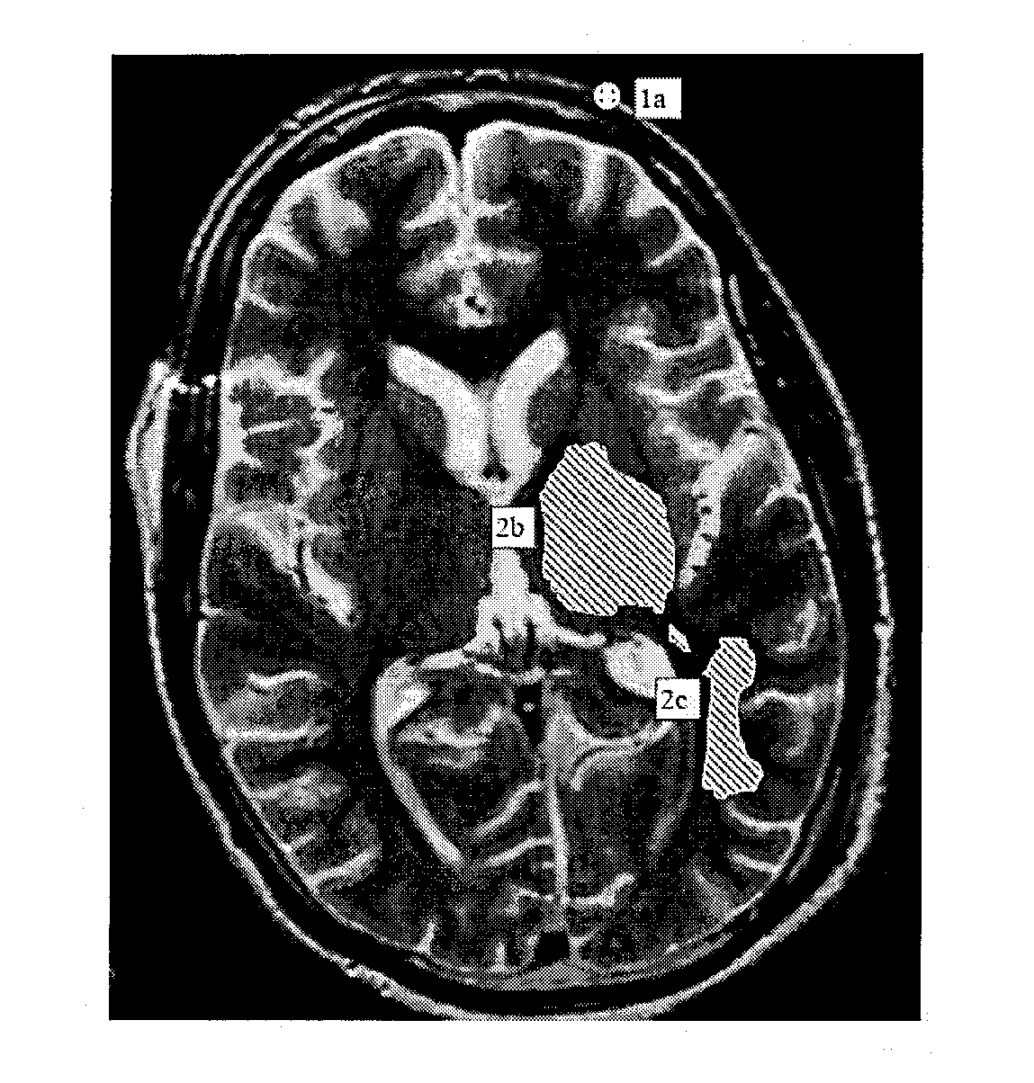
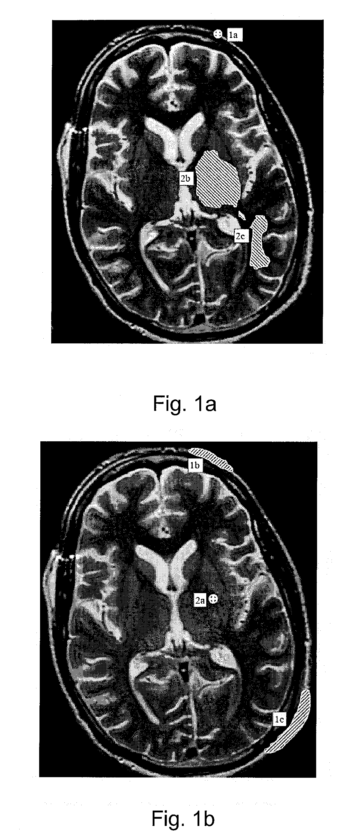
[0034]FIG. 1A shows a first exemplary recording of the structure and anatomy of a brain, wherein an entry point 1a is specified, for example by a user, in the represented structure and anatomy of the brain. Possible target areas 2b, 2c of the catheter can be determined from the indicated entry point 1a and, for example, lie in such a way that catheter positioning guidelines and the structure and / or the anatomy of the brain can be taken into account when a catheter is inserted or introduced. The catheter positioning guidelines can be the distance between the catheter tip or the catheter delivery section and the surface of the brain, or the distances between the catheter, the catheter tip or the catheter delivery section and characteristic regions of the brain such as cavities, hollows, sulci, or ventricles. The target areas 2b, 2c, determined taking into consideration the catheter positioning guidelines and the individual structure and anatomy of the brain, can be represented in the ...


PUM


Abstract

A method for determining and representing possible entry and/or target areas for positioning catheters in an area on the basis of functional data and/or structural and/or anatomical data of the area, includes: indicating at least one entry area of the catheter or at least one target area of the catheter; determining at least one target area of the catheter based on the at least one indicated entry area of the catheter and taking into consideration specified catheter positioning guidelines and the functional data and/or structural and/or anatomical data of the area, or at least one entry area of the catheter based on the at least one indicated target area of the catheter and taking into consideration specified catheter positioning guidelines and the functional data and/or structural and/or anatomical data of the area; and representing the functional data and/or structural and/or anatomical data with the at least one indicated entry area and the at least one determined target area, or representing the functional data and/or structural and/or anatomical data with the at least one indicated target area and the at least one determined entry area.

Description

RELATED APPLICATION DATA [0001] This application claims priority of U.S. Provisional Application No. 60 / 689,987 filed on Jun. 13, 2005, which is incorporated herein by reference in its entirety.FIELD OF THE INVENTION [0002] The present invention relates to a method and device for determining and representing possible entry and / or target areas for positioning one or more catheters in an area, in particular in tissue regions such as a brain, wherein the area is determined on the basis of structural and / or anatomical data of the area. BACKGROUND OF THE INVENTION [0003] In known methods for positioning one or more catheters, the catheters are positioned on the basis of simple catheter positioning guidelines. In keeping with these guidelines, the catheter tip is often positioned sufficiently deep in a brain region and positioned at a sufficient distance from surfaces to make an infusion agent dispensed from the catheter less likely to discharge into hollows, sulci or back into the cerebr...

Claims


Application Information

Patent Timeline
IPC IPC(8): A61B5/05
CPCA61B19/201A61B19/52A61B19/5244A61M2005/14292A61B2019/5251A61B2019/5255A61B2019/566A61B2019/507A61B34/20A61B90/11A61B90/36A61B2034/107A61B2034/2051A61B2034/2055A61B2034/256
Inventor HARTLEP, ANDREASPEDAIN, CHRISTOPH
Owner BRAINLAB
Why Eureka
Try Eureka