Systems and methods for receiving the output of a direct steam injector

a direct steam injection and output technology, applied in the direction of milk preservation, lighting and heating apparatus, egg preservation by heating, etc., can solve the problems of increased operating costs of such systems, steam injection systems, and deposition of materials from products, so as to reduce or eliminate the deposition of product constituents and increase the run time

Pending Publication Date: 2020-08-27
FREEZING MACHINES
View PDF66 Cites 0 Cited by
  • Summary
  • Abstract
  • Description
  • Claims
  • Application Information

AI Technical Summary

Benefits of technology

[0010]It is an object of the invention to provide direct steam injection systems and direct steam injection methods which reduce or eliminate the deposition of product constituents on surfaces within the injection system downstream from the injector. This reduction or elimination of deposits increases run time for products such as milk and allows heat treatment of products, such as those including meat proteins or egg proteins for example (especially raw meat or egg proteins), that could not previously be treated by direct steam injection due to high deposition rates within the product flow paths and consequent plugging. It is also an object of the invention to provide a product produced by the direct steam injection methods described below.
[0012]According to the various aspects of the present invention described below, at least some of the surfaces of the injection system that come in contact with the mixture of steam and product being treated are cooled by a suitable cooling arrangement to at least reduce the rate at which product constituents form deposits on those surfaces. In particular, certain surfaces which make up a product and steam mixture flow path within a vacuum chamber of the steam injection system are cooled by a suitable cooling arrangement. It has been found that cooling some of these surfaces prevents undue deposition of product constituents, even in cases where the product being treated comprises a product that could not previously be treated by direct steam injection, such as products including raw meat or egg proteins for example.
[0015]The use of cooling structures along at least some of the mixture flow path within the vacuum chamber volume and the removal of heat along this portion of the mixture flow path allows the temperature of surfaces making up the flow path in these locations to be maintained below temperatures at which the product tends to form deposits on the surfaces. This at least reduces the rate at which constituents from the product are deposited on those surfaces during operation of the system. This reduction of deposition rate allows the system to be operated longer between cleaning procedures during which the system must be taken out of operation. In some cases, the reduction of deposition rate allows the system and method to be used for products that could not be treated using prior art direct steam injection systems and methods. Such products encompass products which include raw meat or egg proteins, that is, meat or egg proteins which have not been denatured by cooking, and particularly raw fibrous meat proteins. Systems and methods according to the present invention may thus be used, for example, to pasteurize materials including raw meat or egg proteins which remain undenatured in the course of pasteurization. As used herein, “meat protein” includes proteins derived from the meat of any animal including, mammals, fish, and birds. As used herein, “egg protein” includes proteins derived from chicken and similar eggs. Beyond the application to the pasteurization of raw meat or egg proteins, aspects of the present invention have application in heat treating many types of products for many purposes.
[0023]Some embodiments according to either aspect of the present invention may include essentially no hold conduit which extends through a vacuum chamber wall and into the vacuum chamber volume. In these embodiments the mixture flow path, and particularly the portion of the mixture flow path within the vacuum chamber volume may be defined by an inner surface of a dispersal wall which comprises one of the walls of the vacuum chamber defining the vacuum chamber volume. In these embodiments the heated mixture exits the hold conduit and spreads out within the vacuum chamber along the dispersal wall to enhance the effect of the vacuum on the material as will be described further below in connection with the illustrated examples.

Problems solved by technology

Although direct steam injection systems are commonly used for heat treating foodstuffs such as milk and juices, problems remain which increase the cost of operating such systems.
Perhaps the most persistent problem encountered in direct steam injection systems is the deposition of materials from the product, milk proteins in the case of milk treatment for example, on surfaces within the steam injector and downstream from the injector.
This removal of deposits necessitates the shut-down of the treatment system and these shut downs increase operation costs and reduce productivity.
In applications beyond dairy products, deposition may be so rapid that passages carrying the product to be treated become completely plugged in a very short period of time, a few seconds or a few minutes.
The deposition problem thus prevents prior direct steam injection systems from being used for heat treating certain products, such as products including meat proteins or egg proteins, especially raw (that is, uncooked) meat proteins in fibrous and other forms.
While the surface washing and surface cooling in the injector downstream from the injection point may be effective to increase run times for some products, the techniques shown in U.S. Pat. No. 3,988,112 do not eliminate product deposition and may be entirely ineffective for some types of products.
Also, the surface washing shown in U.S. Pat. No. 3,988,112 may lead to uneven heating in the product to be treated and may reduce the effectiveness of the heat treatment with regard to eliminating pathogens.
However, the use of PEEK within the injector disclosed in U.S. Patent Application Publication No. 2016 / 0143343 does not eliminate product deposition and thus the injection system disclosed in this publication relies on a sensor arrangement which can be used to adjust flow paths within the injector to help ensure the desired level of heating in the product as deposits form on the injector surfaces.

Method used


Image

  • Systems and methods for receiving the output of a direct steam injector
  • Systems and methods for receiving the output of a direct steam injector
  • Systems and methods for receiving the output of a direct steam injector

Examples


Embodiment Construction

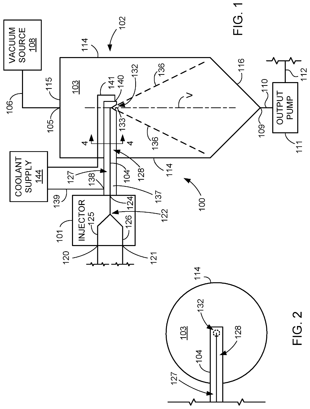
[0034]Referring to FIG. 1, a steam injection system 100 includes a steam injector 101 and a vacuum chamber 102. Vacuum chamber 102 includes a vacuum port 105 connected by a suitable vacuum conduit 106 to a vacuum source 108, and also includes an outlet port 109 connected by a suitable product outlet conduit 110 to an output pump 111. Steam injection system 100 also includes a mixture flow path which extends from injector 101 to vacuum chamber 102. In this case the mixture flow path is defined by a hold conduit 104 extending from steam injector 101 to a location within the interior of vacuum chamber 102, that is, a location within vacuum chamber volume 103.

[0035]Vacuum chamber 102 comprises a suitable vessel which defines the vacuum chamber volume 103. In particular, vacuum chamber 102 includes lateral walls 114, a top wall 115 and cone-shaped bottom wall 116 which together define vacuum chamber volume 103. As indicated in FIG. 1 vacuum chamber 102 may be elongated along a vertical a...


PUM

PropertyMeasurementUnit
temperatureaaaaaaaaaa
thermal conductivityaaaaaaaaaa
temperaturesaaaaaaaaaa

Abstract

A system includes a vacuum chamber, a vacuum source, and a mixture flow path adapted to be connected to receive the output of a direct steam injector. The vacuum source is operatively connected to a vacuum port of the vacuum chamber, while a product outlet port from the vacuum chamber is adapted to be connected to an arrangement for removing treated product from the vacuum chamber. The mixture flow path includes a flow path segment outside of the vacuum chamber volume and a flow path segment within the vacuum chamber volume. At least some of a surface defining the flow path segment within the vacuum chamber is in substantial thermal communication with one or more cooling structures.

Description

CROSS-REFERENCE TO RELATED APPLICATION[0001]Applicant claims the benefit, under 35 U.S.C. § 119(e), of U.S. Provisional Patent Application No. 62 / 808,778 filed Feb. 21, 2019, and entitled “Direct Heating Medium Injector and Injection System and Method.” The entire content of this provisional application is incorporated herein by this reference.TECHNICAL FIELD OF THE INVENTION[0002]The invention relates to apparatus and methods for neutralizing pathogens in materials, particularly foodstuffs, by steam injection.BACKGROUND OF THE INVENTION[0003]Heat treatment is used in the food processing industry to eliminate pathogens and for other purposes. For example, milk may be heated to about 145° for about thirty minutes, or to about 162° F. for about fifteen seconds to destroy or deactivate disease-causing microorganisms found in milk. These heat treatment processes are commonly referred to as pasteurization. Milk or cream may also be treated by heating to 280° F. to 302° F. for two to six ...

Claims


Application Information

Patent Timeline
Patent Type & Authority Applications(United States)
IPC IPC(8): A23C3/037A23L3/00A23L3/22F28C3/06F28D3/04
CPCF28C3/06A23L3/22A23L3/001A23L3/003F28D3/04A23C3/037A23V2300/24A23L3/18A23B4/0053A23B5/005A23V2002/00A23B5/0055B01F23/23B01F23/23121
Inventor ROTH, NICHOLAS A.
Owner FREEZING MACHINES
Why Eureka
Try Eureka