Vascular Access Device and Related Method

Inactive Publication Date: 2020-09-03
PRYTIME MEDICAL DEVICES INC
View PDF0 Cites 3 Cited by
  • Summary
  • Abstract
  • Description
  • Claims
  • Application Information

AI Technical Summary

Benefits of technology

The patent is about an access device for blood vessels that allows for the placement of a needle and guidewire. The device has a body with a guidewire channel and a needle with a funnel-like port that can be connected to the guidewire. The device also has a flash channel that allows for blood flow between the guidewire and the channel. The technical effects of this device are improved access to blood vessels for interventional procedures, making it easier to treat blockages and other vascular issues.

Problems solved by technology

The tip of the needle is inserted through the patient's skin and into the blood vessel (vein or artery), which may be difficult to locate and pierce due to differing patient anatomy.
In addition, the proper placement of the needle in the blood vessel may be difficult to confirm due to limited pressure in the blood vessels (particularly in veins), positioning of different blood vessels near each other, patient anatomy and other factors.
Proper positioning may, however, be lost while the medical professional reaches for and attempts to insert a guidewire into the needle or access device.
The physician's or medical technician's movement to retrieve the guidewire can result in movement of the tip of the needle, potentially resulting in the tip moving out of the blood vessel.
Feeding the guidewire into the proximal end of the needle or connector following retrieval can also be difficult, resulting in additional potential for movement of the tip out of the blood vessel and delay in the procedure.
For example, the physician may need to re-start the procedure of positioning the tip of the needle in the vessel if the tip moves out of the vessel or may need to re-arrange the tip back into the appropriate vessel, thereby delaying the procedure and often increasing patient discomfort.
Feeding the guidewire into the proximal end of the needle is particularly difficult when the needle has a small diameter at its proximal end, the distal end of the guidewire has a J-shape that is preferably straightened before insertion into the proximal end of the needle and / or the medical professional is rushing the procedure, particularly in trauma situations.
This multiple step process and exchange of components, including the needle, syringe, other instrument and guidewire may cause pain for the user and provides multiple opportunities for the needle or guidewire to move or become misaligned, potentially requiring the medical professional to re-start the procedure or realign the components, particularly the tip of the needle before the guidewire is inserted into the vessel.
In addition, the relatively short length of the cheater results in a relatively flexible distal portion of the guidewire extending out of the proximal end of the cheater when loaded, which can cause the guidewire to slide or fall out of the cheater unless the technician is holding the guidewire into the cheater.
Further, the relatively flexible distal portion of the guidewire may buckle between the proximal end of the cheater and the stiffer portion of the guidewire when the technician initially attempts to urge the guidewire into the needle and patient because the relatively flexible portion of the distal tip of the guidewire is not supported by the cheater.
These access devices are typically limited for use with predetermined guidewire sizes that correlate with the size of the integrated hypodermic or vascular access needle.
These internal channels are difficult to clean and / or sterilize after blood or other fluids flow through the internal channels and are not reusable in most situations following an initial flash or blood flow.
When the user tries to advance the guidewire, it jams because the needle tip is no longer in the blood vessel.
Cleaning and sterilization are difficult because of the small diameter of the needle lumen.

Method used


Image

  • Vascular Access Device and Related Method
  • Vascular Access Device and Related Method
  • Vascular Access Device and Related Method

Examples


Embodiment Construction

[0040]Certain terminology is used in the following description for convenience only and is not limiting. Unless specifically set forth herein, the terms “a”, “an” and “the” are not limited to one element but instead should be read as meaning “at least one”. The words “right”, “left”, “lower” and “upper” designate directions in the drawings to which reference is made. The words “inwardly” or “distally” and “outwardly” or “proximally” refer to directions toward and away from, respectively, the patient's body, or the geometric center of the preferred access device and related parts thereof. The words, “anterior”, “posterior”, “superior,”“inferior”, “lateral” and related words and / or phrases designate preferred positions, directions and / or orientations in the human body to which reference is made and are not meant to be limiting. The terminology includes the above-listed words, derivatives thereof and words of similar import.

[0041]It should also be understood that the terms “about,”“app...


PUM


Abstract

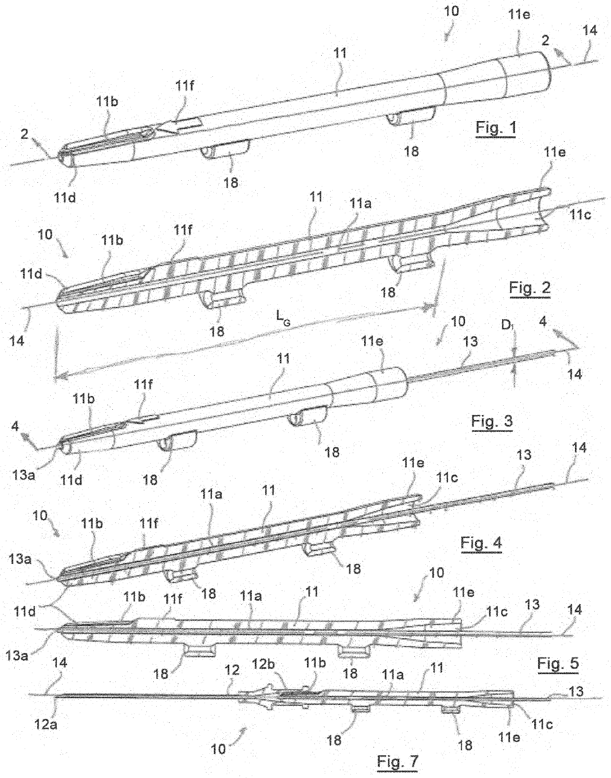
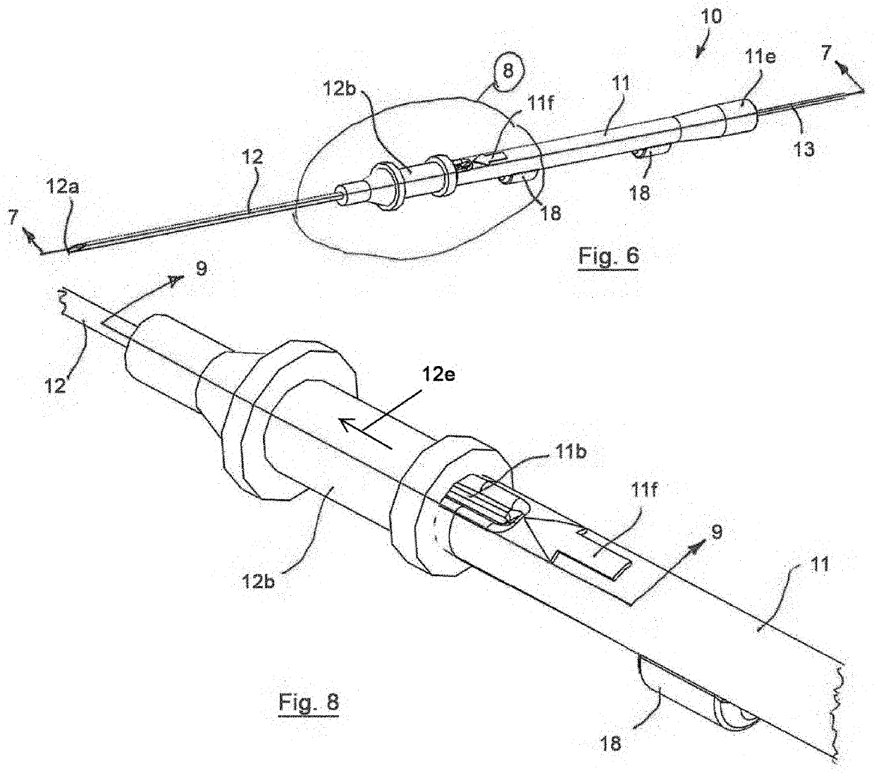
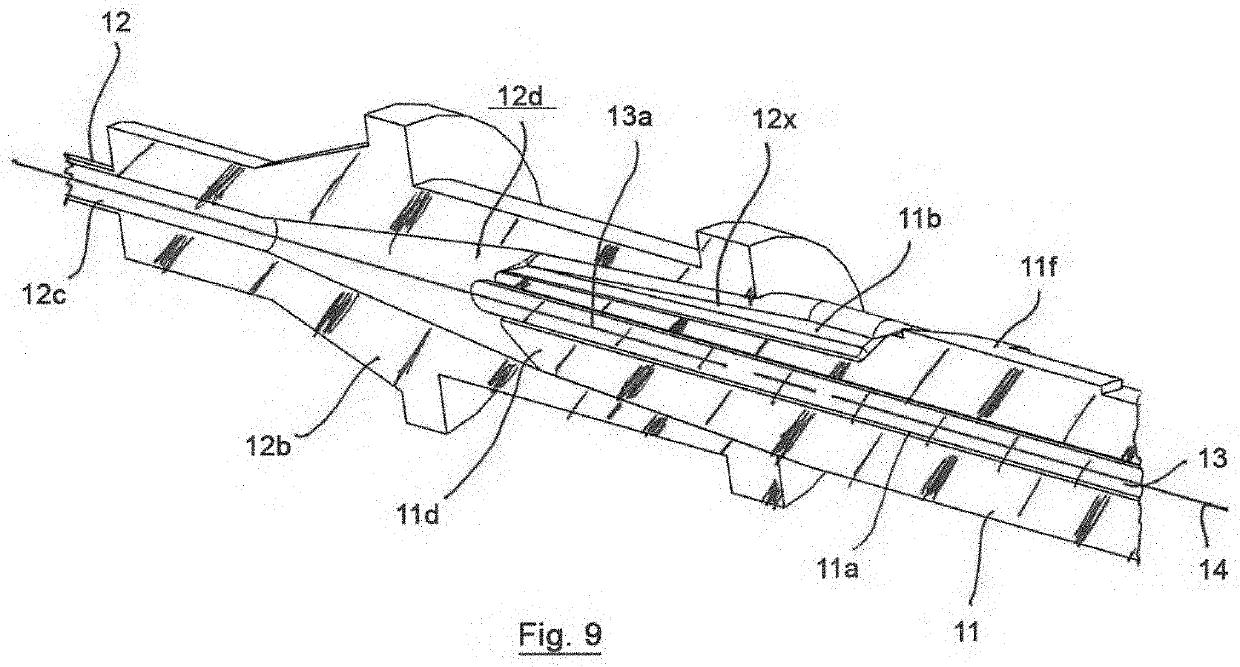
An access device includes a body, a needle and a guidewire. The body has a guidewire channel extending from a distal end of the body toward the proximal end. The guidewire channel opens into a funnel-like port having a proximal port diameter greater than a distal port diameter. The distal port diameter is substantially the same as a guidewire channel diameter. The needle has a tip, a proximal end and a needle lumen. The proximal end of the needle is removably secured to a distal end of the body in an assembled configuration. A guidewire has a front end portion positioned in the guidewire channel in an initial configuration and a guidewire diameter. The guidewire channel diameter is greater than the guidewire diameter and the guidewire channel facilitates blood flow between the guidewire and an internal surface of the guidewire channel when the guidewire is positioned in the guidewire channel.

Description

BACKGROUND OF THE INVENTION[0001]Known arterial and vascular access procedures are conducted using a cannula needle and guidewire as distinct and separate components. Vascular access procedures may also utilize a separate syringe that is attached to a connecting portion to draw a vacuum on the needle and withdraw blood from the vein when the needle tip is positioned within the vein. The tip of the needle is inserted through the patient's skin and into the blood vessel (vein or artery), which may be difficult to locate and pierce due to differing patient anatomy. In addition, the proper placement of the needle in the blood vessel may be difficult to confirm due to limited pressure in the blood vessels (particularly in veins), positioning of different blood vessels near each other, patient anatomy and other factors. Appropriately positioning the needle tip in the vein may be facilitated by pulling a vacuum in the needle using a separately attached syringe to draw blood from the vessel...

Claims


Application Information

Patent Timeline
IPC IPC(8): A61M25/09A61M25/06
CPCA61M25/0693A61M25/065A61M25/09041
Inventor FRANKLIN, CURTIS J.KRUMMENACHER, TODD J.REYNOLDS, JEREMY
Owner PRYTIME MEDICAL DEVICES INC
Why Eureka
Try Eureka