Fuel cell assembly and cell unit for a fuel cell stack

Active Publication Date: 2020-09-03
AUDI AG
View PDF0 Cites 1 Cited by
  • Summary
  • Abstract
  • Description
  • Claims
  • Application Information

AI Technical Summary

Benefits of technology

[0016]This design has the advantage that now two different media can reach the active area via the edge region. These are preferably the two reaction media of a fuel cell system; however, it is also possible for a cooling medium to be used. Moreover, with this design, the active area can still be maximized and, with a corresponding design of the sealing tongues, the edge region can be minimized.
[0017]In order to be able to connect the first bipolar plate and the second bipolar plate to one another in an operationally reliable and gas-tight manner, it has proven to be useful if a composite layer having recesses is provided between the first bipolar plate and the second bipolar plate. This composite layer is designed to laterally seal in a gas-tight manner the active area. One or more media channels are kept free in the region of the recesses. This ensures that, as a result of the composite layer, no media channels, for example media inlet channels or media outlet channels, are sealed or blocked by the composite layer. The composite layer is to be understood here as a joining layer which is formed from a joining material for joining the first bipolar plate

Problems solved by technology

This design is disadvantageous because, due to the passage extending perpendicularly through the memb

Method used


Image

  • Fuel cell assembly and cell unit for a fuel cell stack
  • Fuel cell assembly and cell unit for a fuel cell stack
  • Fuel cell assembly and cell unit for a fuel cell stack

Examples


Example

[0038]It should be noted in advance that the dimensions, proportions and scale of the illustrations shown are not specified and may vary. In particular, in the sectional illustrations, the individual layers are represented in such a way that it is possible to understand the mutual position in which and the order in which the individual layers are stacked on top of each other.

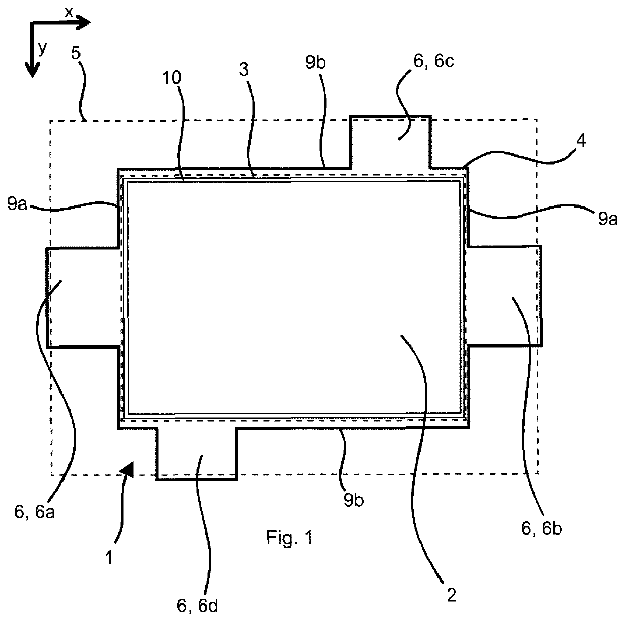
[0039]FIG. 1 shows a fuel cell arrangement 1 which comprises a membrane electrode assembly 2 arranged in its center with a cathode, an anode and a proton-conductive membrane arranged between the cathode and the anode. This membrane electrode assembly 2 essentially predetermines an active area 3, which is sketched in the figure by the inner dashed line. This active area 3 extends not only in a plane (x / y plane) but also in a stacking direction of the membrane electrode assembly 2 (z direction), which is directed out of the paper plane.

[0040]The active area 3 is the region in which the electrochemical reaction of ...


PUM


Abstract

A fuel cell arrangement with a membrane electrode assembly is provided which comprises a cathode, an anode and a membrane arranged between the cathode and the anode, with an active area essentially predetermined by the membrane electrode assembly, and with a sealing structure laterally assigned to the membrane electrode assembly. The sealing structure comprises a sealing tongue extending into or over an edge region outside the active area for axially covering in a gas-tight manner a media channel formed in an adjacent bipolar plate and located in the edge region. A unit cell for a fuel cell stack with such a fuel cell arrangement is also provided.

Description

BACKGROUNDTechnical Field[0001]Embodiments of the invention relate to a fuel cell arrangement and a unit cell for a fuel cell stack with such a fuel cell arrangement.Description of the Related Art[0002]In particular, a fuel cell arrangement comprises a membrane electrode assembly comprising a cathode, an anode and a membrane arranged between the cathode and the anode. The membrane electrode assembly or its dimensions essentially predetermine an active area, in which the electrochemical reaction of a fuel cell takes place.[0003]A sealing structure which in particular ensures that the reaction media can only flow where they are required for the electrochemical reaction is laterally assigned to the membrane electrode assembly.[0004]DE 19703214 C 1 shows a fuel cell arrangement. In this case, a seal is attached to or impregnated into the edge of the cathode and the anode of the membrane electrode assembly. In order to supply a medium to the anode or the cathode, a perpendicular supply l...

Claims


Application Information

Patent Timeline
IPC IPC(8): H01M8/0273H01M8/0258H01M8/1004H01M8/2485
CPCH01M8/0273H01M8/2485H01M8/0258H01M8/1004H01M8/10H01M8/2484H01M8/24H01M8/0271H01M8/0276Y02E60/50H01M8/242H01M2008/1095
Inventor GRETZER, MARKUSKLUY, NORBERT
Owner AUDI AG
Why Eureka
Try Eureka