Solid-oxide fuel cell module for a fuel cell stack

a fuel cell module and solid-oxide technology, applied in the field of hydrogen/oxygen fuel cells, can solve the problems of reducing failure of seal joints, catastrophic collapse of stack structures, etc., and achieve the effect of maximizing the active area of cells

Inactive Publication Date: 2007-09-18
DELPHI TECH INC
View PDF18 Cites 33 Cited by
  • Summary
  • Abstract
  • Description
  • Claims
  • Application Information

AI Technical Summary

Benefits of technology

[0010]Briefly described, a fuel cell module in accordance with the invention has four sheet metal parts stamped from flat stock which do not require any forming operations such as folding or dishing. Each part has a different thickness to suit its function. Because the parts are flat, stacked on top of one another, and metallurgically joinable, the cell active area is maximized because there is no wasted space in radial corners.

Problems solved by technology

However, this fabrication method requires space for radius of the forming folds which reduces space available for cell active area when the overall volume of the assembly is fixed by use constraints.
In addition, there are regions in the sealing surfaces between one cell / frame assembly and the next where the metal parts are unsupported or cantilevered.
As a result, the metal parts can creep at the high operating temperatures required for a solid-oxide fuel cell, causing failure in the seal joints and potentially a catastrophic collapse of the stack structure.
Other fabrication methods often used require costly machining of the components used in the frame and interconnect assembly.

Method used


Image

  • Solid-oxide fuel cell module for a fuel cell stack
  • Solid-oxide fuel cell module for a fuel cell stack
  • Solid-oxide fuel cell module for a fuel cell stack

Examples


Embodiment Construction

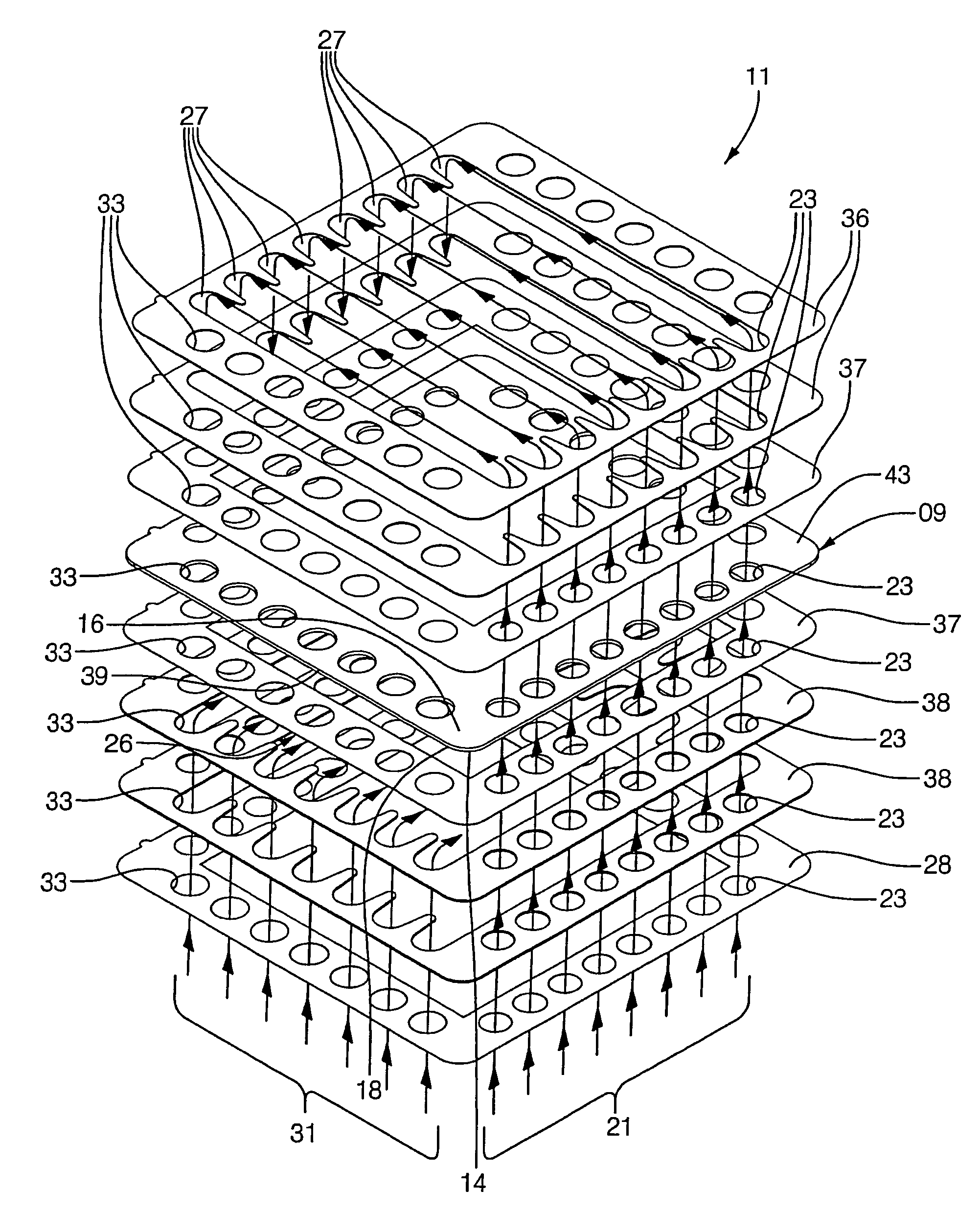
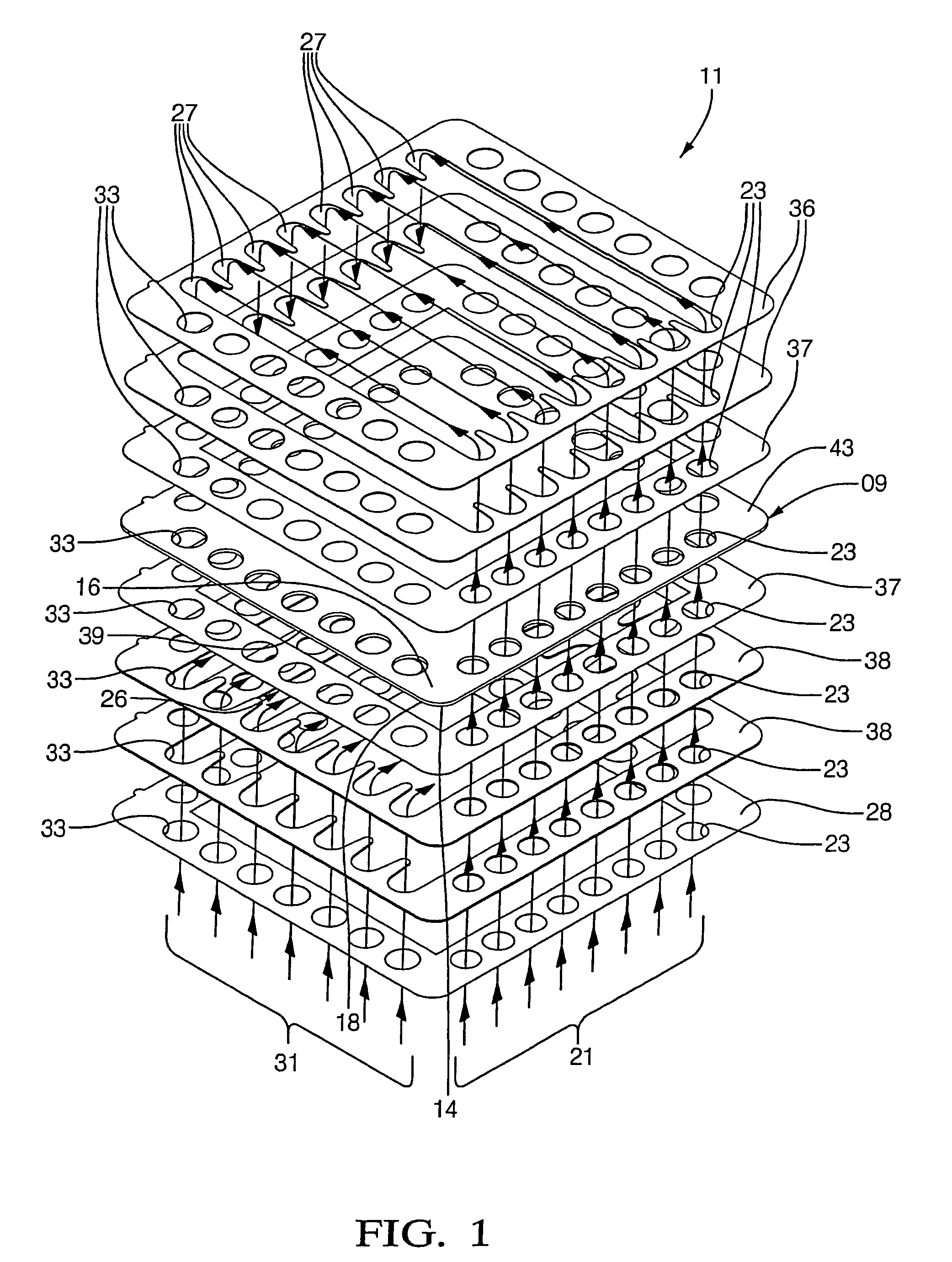
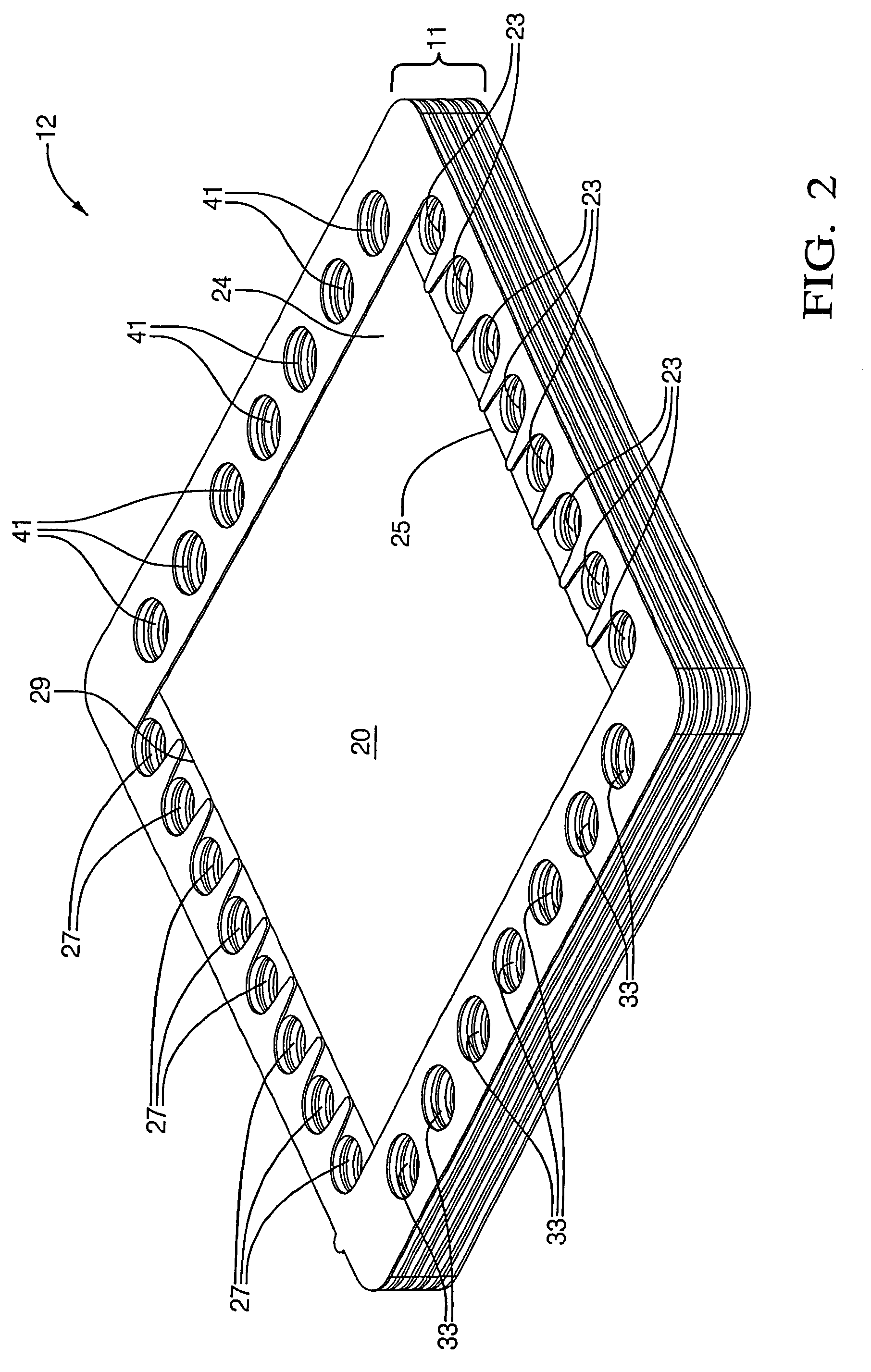
[0024]FIGS. 1 through 3 are useful in describing generally the structure of a multiple fuel cell stack assembly. FIGS. 4 through 10 are illustrative of improved fuel cell assemblies in accordance with the invention.

[0025]Referring to FIGS. 1 and 2, an individual fuel cell 11 includes a multilayer fuel cell element 09 comprising an electrolyte 14 (E) having an anode 16 or positive element (P) deposited on a first surface thereof and a cathode 18 or negative element (N) deposited on a second surface thereof. Thus, element 09, which is the actual “fuel cell,” is known in the art by the acronym PEN. Passage 24 for flow of fuel 21 across the free surface 20 of anode 16 is provided by first cut-out spacers 36 sealed to anode 16 by peripheral seal 37, and passage 26 for flow of air 31 across the free surface of cathode 18 is provided by second cut-out spacers 38 sealed to cathode 18 by another peripheral seal 37. Fuel 21, typically in the form of hydrogen or reformate gas, is provided at a...


PUM

PropertyMeasurementUnit
voltageaaaaaaaaaa
voltageaaaaaaaaaa
thicknessaaaaaaaaaa

Abstract

A fuel cell module having four sheet metal parts stamped from flat stock. The parts do not require any forming operations such as folding or dishing. Each part may have a different thickness to suit its function. The first part is a cell mounting frame for receiving and supporting a PEN fuel cell element. The second part is a cathode spacer, the thickness of the spacer determining the height of the cathode air flow field. The third part is an anode spacer, the thickness of spacer determining the height of the anode fuel flow field. The fourth part is a separator plate for separating the anode gas flow in one cell from the cathode air flow in an adjacent cell in a fuel cell stack. The four plates are joined by welding or brazing and may be assembled in any order or combination which suits the assembly process. Any desired number of modules may be stacked together to form a fuel cell stack.

Description

STATEMENT REGARDING FEDERALLY SPONSORED RESEARCH OR DEVELOPMENT[0001]This invention was made with United States Government support under Government Contract No. DE-FC26-02NT41246. The Government has certain rights in the invention.TECHNICAL FIELD[0002]The present invention relates to hydrogen / oxygen fuel cells; more particularly, to fuel cell stacks comprising a plurality of individual cells connected by interconnect elements; and most particularly, to a fuel cell module formed of four stamped metal plates and a PEN element.BACKGROUND OF THE INVENTION[0003]Fuel cells which generate electric current by the electrochemical combination of hydrogen and oxygen are well known. In one form of such a fuel cell, an anodic layer and a cathodic layer are deposited on opposite surfaces of an electrolyte formed of a ceramic solid oxide. Such a fuel cell is known in the art as a “solid oxide fuel cell” (SOFC). Hydrogen, either pure or reformed from hydrocarbons, is flowed along the outer surface...

Claims


Application Information

Patent Timeline
Patent Type & Authority Patents(United States)
IPC IPC(8): H01M2/00H01M2/02H01M2/14H01M8/02H01M8/24
CPCH01M8/0273H01M8/242H01M8/2425H01M8/0247Y02E60/50H01M8/2432H01M8/2483
Inventor HALTINER, JR., KARL J.SIMPKINS, HASKELLMUKERJEE, SUBHASISH
Owner DELPHI TECH INC
Why Eureka
Try Eureka