Monitoring system

a technology of monitoring system and monitoring state, applied in the direction of measuring using digital techniques, instruments, electric devices, etc., can solve the problem that the information relating to the action state cannot be obtained from the power generation system

Inactive Publication Date: 2020-09-17
ORMON CORP
View PDF0 Cites 0 Cited by
  • Summary
  • Abstract
  • Description
  • Claims
  • Application Information

AI Technical Summary

Problems solved by technology

Therefore, the action state of the power storage system can also be accurately grasped, but when the power generation system is made by another company or when the power generation system does not have a function of outputting the information relating to the action state to an external device, the information relating to the action state cannot be obtained from the power generation system.

Method used


Image

  • Monitoring system
  • Monitoring system
  • Monitoring system

Examples


application examples

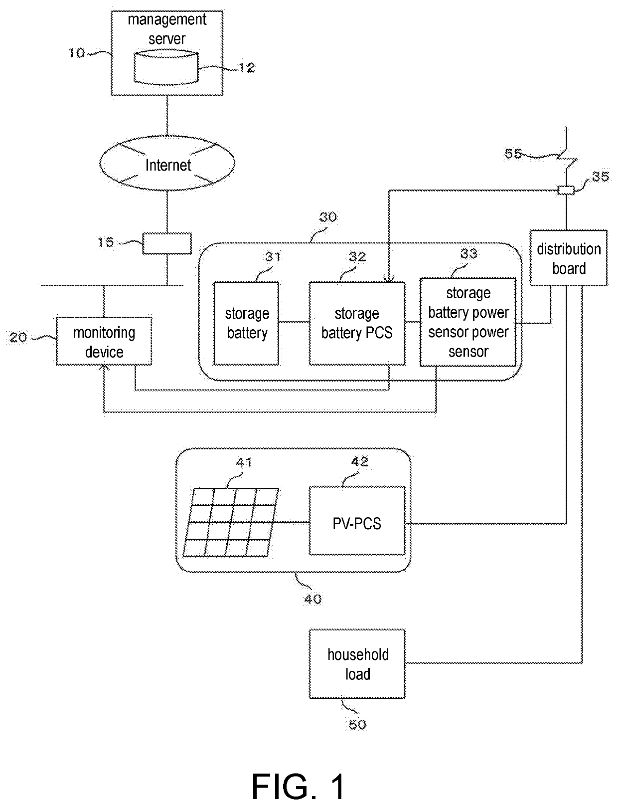
[0034]Application examples of the disclosure are described below with reference to the drawings. FIG. 1 is a diagram illustrating a schematic configuration and a usage state of a monitoring system according to Example 1 of the disclosure.[0035]A power generation system 40 may be made by another company, or the power generation system 40 may not have a function of outputting information relating to an action state to an external device. In this case, in order to diagnose presence or absence of abnormality in the power generation system 40 connected to a power receiving point 55 the same as a power storage system 30 without obtaining any information from the power generation system 40, it is conceivable to detect a failure of the power generation system by monitoring power reversely flowed from the power receiving point 55 to a system.

[0036]In general, when the power storage system 30 and the power generation system 40 are used in combination, there are a power sale priority mode whic...

example 1

[0045]A monitoring system according to Example 1 of the disclosure is described more specifically below using the drawings.

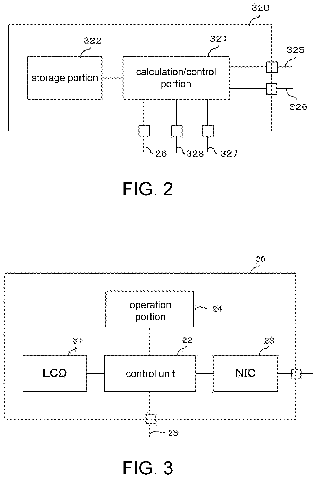
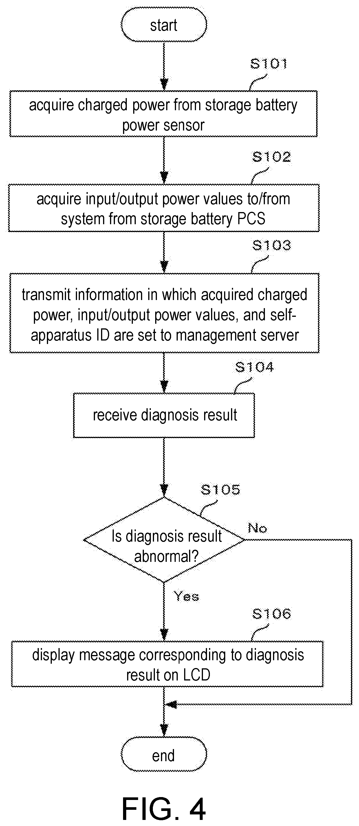
[0046][0047]An overview of the monitoring system according to the example of the disclosure is described using FIG. 1, FIG. 2 and FIG. 3. FIG. 1 is an illustrative diagram of a schematic configuration and a usage form of the monitoring system according to the example, FIG. 2 is a schematic configuration diagram of a controller of a storage battery PCS, and FIG. 3 is a schematic configuration diagram of a monitoring device which is a component of the monitoring system.

[0048]As shown in FIG. 1, the monitoring system according to the example includes a management server 10, a power storage system 30 combined with a power generation system 40, and a monitoring device 20. Moreover, “combined with the power generation system 40” means “connected to a power receiving point 55 to which the power generation system 40 is connected”. In addition, FIG. 1 shows one power sto...

example 2

[0098]A monitoring system according to Example 2 of the disclosure is described below more specifically using the drawings.[0099]Configurations and processes in common with Example 1 are denoted by the same reference signs, and detailed description thereof is omitted.[0100]The schematic configuration and the usage form of the monitoring system according to the example, the schematic configuration of the controller 320 of the storage battery PCS 32, and the schematic configuration of the monitoring device 20 are the same as those of Example 1.[0101]In Example 1, the monitoring device 20 acquires charged power from the storage battery power sensor 33, acquires input / output power values to / from the system from the storage battery PCS 32, and transmits information in which these data and the self-apparatus ID are set to the management server 10. Then, the charged power amount (self-consumption) is calculated by the management server 10. In contrast, in the example, in the storage batter...


PUM


Abstract

The monitoring system includes: a management server, and a transmission device which obtains, from the power storage system, first charged power index values indicating charged power of the power storage system and input/output power index values indicating input/output power from the power receiving point to which the power storage system is connected to a system, and transmits the index values to the management server via a network. The management server includes: a calculation part which calculates, based on the first charged power index values and the input/output power index values, second charged power index values indicating power charged by generated power of the power generation system connected to the power receiving point of charged power of the power storage system; and a diagnosis part which diagnoses presence or absence of abnormality of the power generation system based on the second charged power index values calculated by the calculation part.

Description

CROSS-REFERENCE TO RELATED APPLICATION[0001]This application claims the priority benefits of Japan Patent Application No. 2019-043668, filed on Mar. 11, 2019. The entirety of the above-mentioned patent application is hereby incorporated by reference herein and made a part of this specification.BACKGROUND OF THE DISCLOSURETechnical Field[0002]The disclosure relates to a monitoring system.Related Art[0003]Conventionally, in order to be able to confirm (grasp) an action state of an apparatus with a smartphone or the like, information relating to the action state of the apparatus is collected by a management server on the Internet (for example, see patent literatures 1 (Japanese Patent Laid-Open No. 2000-076033) and patent literatures 2 (Japanese Patent Laid-Open No. 2007-221565)).[0004]Similarly, for a power storage system, information relating to an action state is collected by a management server on the Internet.[0005]When a power storage system is used alone, the action state of the...

Claims


Application Information

Patent Timeline
Patent Type & Authority Applications(United States)
IPC IPC(8): G01R19/25G01R21/00H02J13/00
CPCG01R19/2513H02J13/00001G01R21/005G01R31/36G01R31/52H02J3/381H02J7/35H02J2300/24H02J2310/12H02J13/00004Y02E10/56
Inventor AONO, KUNIOOZEKI, HIDEKIMINATO, ATSUOIMAMURA, KAZUYOSHI
Owner ORMON CORP
Why Eureka
Try Eureka