
Display apparatus, optical element, and electronic apparatus

a technology of optical elements and electronic components, applied in the direction of optics, electrical devices, instruments, etc., can solve the problems of difficult to dispose of the plurality of display areas having different planar shapes in one cell, and achieve the reduction of reflection or the like on the interface, reduce the reflection between the flat plate and the lenticular lens unit, and increase the quality of the image to be displayed

Active Publication Date: 2020-09-24
SONY CORP
View PDF0 Cites 3 Cited by
  • Summary
  • Abstract
  • Description
  • Claims
  • Application Information

AI Technical Summary

Benefits of technology

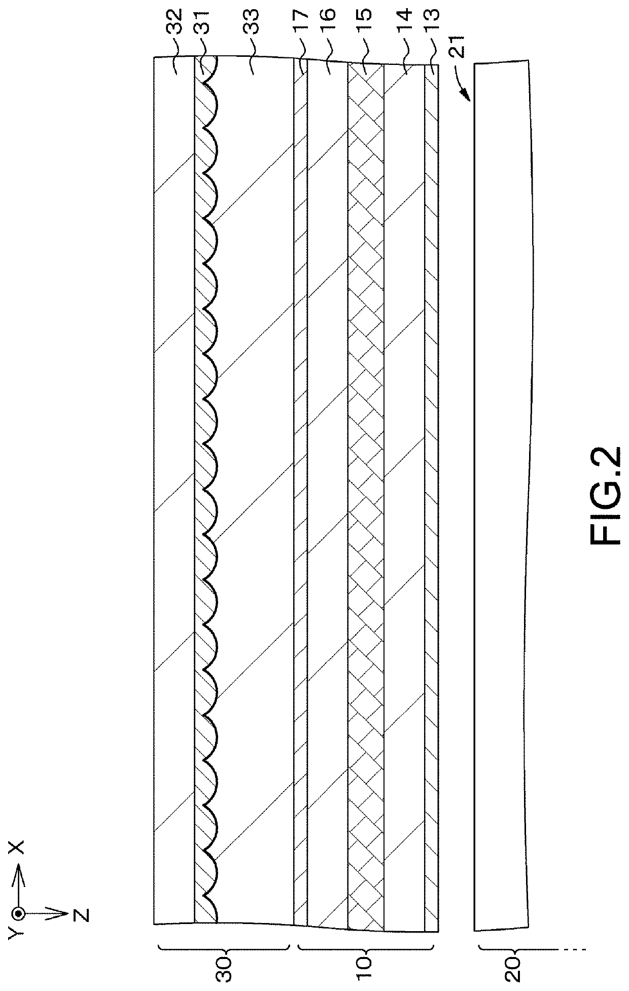
The present technology reduces moire in the display apparatus by controlling the inclination of the structural body of the optical element and reducing reflection between the flat plate and lenticular lens unit, resulting in higher quality images.

Problems solved by technology

However, when an area of the cell is decreased because of the achievement of the high resolution, it becomes difficult to dispose the plurality of display areas having different planar shapes in the one cell.

Method used


Image

  • Display apparatus, optical element, and electronic apparatus
  • Display apparatus, optical element, and electronic apparatus
  • Display apparatus, optical element, and electronic apparatus

Examples


first embodiment

2. First Embodiment

[0057]3. Application example (example of electronic apparatus) and the like

GENERAL DESCRIPTION RELATING TO DISPLAY APPARATUS, OPTICAL ELEMENT, AND ELECTRONIC APPARATUS ACCORDING TO PRESENT TECHNOLOGY

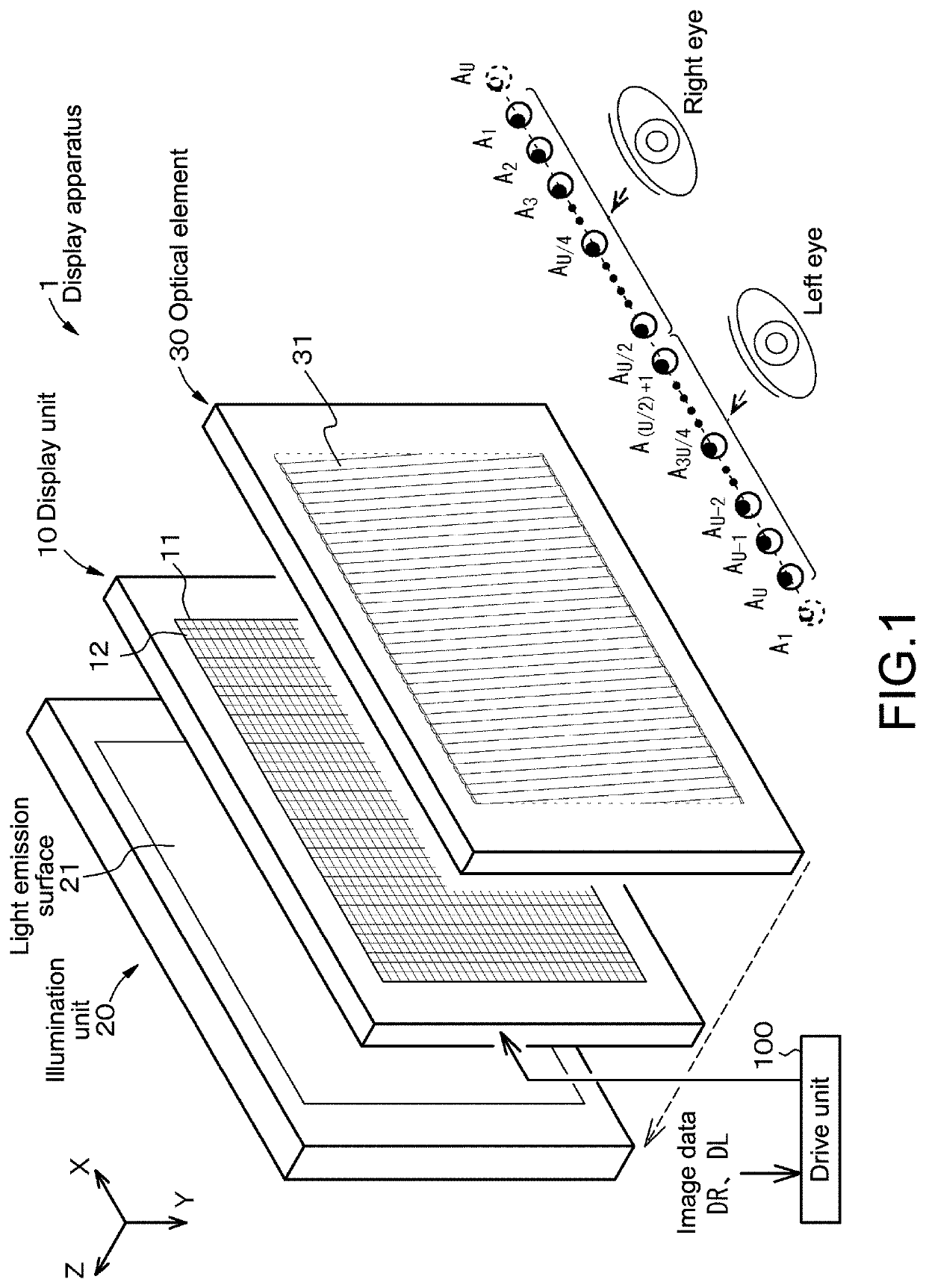
[0058]In a display apparatus according to the present technology or a display apparatus used in an electronic apparatus according to the present technology (hereinafter, those may simply be referred to as “display apparatus according to the present technology” collectively), the following configuration can be achieved:

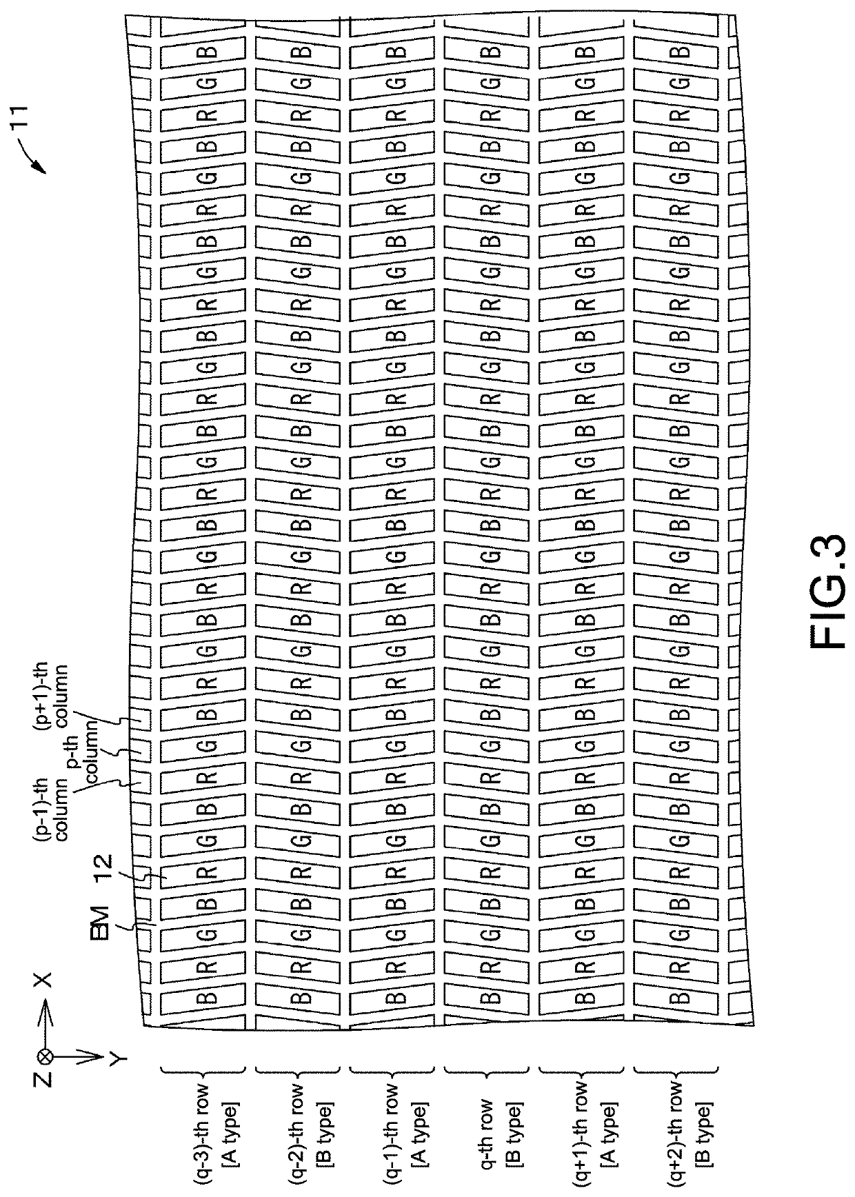
[0059]pixels in a display area configure groups constituted of three pixels arranged in a row direction, and

[0060]when a horizontal pitch of a structural body of an optical element using the number of pixels as a unit is represented by a symbol LMX,

[0061]an inclination of the structural body using the number of pixels as a unit is represented by a symbol SL,

[0062]a vertical displacement using the number of pixels as a unit between a vertical center positi...

application examples (

EXAMPLES OF ELECTRONIC APPARATUS)

[0190]Application examples of the display apparatus described above to an electronic apparatus will be described. As the electronic apparatus, an electronic apparatus for displaying a video signal input from outside or a video signal generated inside thereof as an image or a video can be cited.

application example 1

[0191]FIG. 28A and FIG. 28B each show an external view of a smart phone to which the display apparatus according to the embodiment is applied. Smart phones 200, 200′ includes video display screen units 201, 201′, for example. The video display screen units 200, 201′ are each configured by the display apparatus according to the embodiment described above. By applying the display apparatus according to the embodiment described above, it is possible to display a stereoscopic image with less crosstalk, which can contribute to an enhancement of quality of the smart phones 200, 201′.


PUM

PropertyMeasurementUnit
thicknessaaaaaaaaaa
elastic modulusaaaaaaaaaa
sizeaaaaaaaaaa

Abstract

A display apparatus includes: a display unit having a display area in which a two-dimensional image is displayed; and an optical element configured by disposing a plurality of structural bodies for separating the image displayed in the display area into images observed at predetermined observation positions arranged at intervals in a horizontal direction. In the display area, pixels are arranged in a matrix pattern in the horizontal direction and in a vertical direction, and pixels having different planar shapes are arranged for each row in a certain cycle, and the structural bodies of the optical element are disposed to be tilted at an inclination which satisfies (J+0.5) / 3 (J: integer of 3 or more) with respect to the vertical direction with a number of pixels as a unit.

Description

TECHNICAL FIELD[0001]The present technology relates to a display apparatus, an optical element, and an electronic apparatus. More specifically, the present technology relates to a display apparatus capable of achieving stereovision by displaying an image with a parallax, an optical element used in a display apparatus capable of achieving stereovision, and an electronic apparatus provided with such a display apparatus.BACKGROUND ART[0002]Various display apparatuses which achieve stereovision by observing an image with parallax by an image observer are known. As a glasses-free display apparatus, a display apparatus has been proposed in which an optical element for optical separation which is constituted of a parallax barrier, a lenticular lens provided with a lens sequence, and the like and a display unit which displays a two-dimensional image and is constituted of a liquid crystal display panel or the like are combined (see, for example, Japanese Patent Application Laid-open No. HEI ...

Claims


Application Information

Patent Timeline
Patent Type & Authority Applications(United States)
IPC IPC(8): G02B30/27G02F1/1335H04N13/30
CPCG02B30/27G02F1/133526H04N13/30G02B30/29
Inventor OGAWA, RYOYANO, TOMOYAMIYAKE, HIDETOMOIWASE, NOBUTAKE
Owner SONY CORP
Learn More