Connector

Active Publication Date: 2020-09-24
SUMITOMO WIRING SYST LTD
View PDF0 Cites 0 Cited by
  • Summary
  • Abstract
  • Description
  • Claims
  • Application Information

AI Technical Summary

Benefits of technology

[0016]Generally, it is considered to make a locking area of a suppressing portion and a locking portion larger to make a locking force of the locking portion to lock the suppressing portion larger. However, in the case of reducing a height of a connector, a large locking margin of the suppressing portion and the locking portion cannot be secured in a vertical direction. However, sin

Problems solved by technology

Further, rattling easily occurs when the shell is accommodated into the housing.
Thus, if the locked portion projects out as described above, it becomes difficult to miniaturize the outer conductor and the connector.
However, according to such a connector, the wires ex

Method used


Image

  • Connector
  • Connector
  • Connector

Examples


Example

[0027]A specific example of the connector of the present disclosure is described below with reference to the drawings. Note that the present disclosure is not limited to these illustrations and is intended to be represented by claims and include all changes in the scope of claims and in the meaning and scope of equivalents.

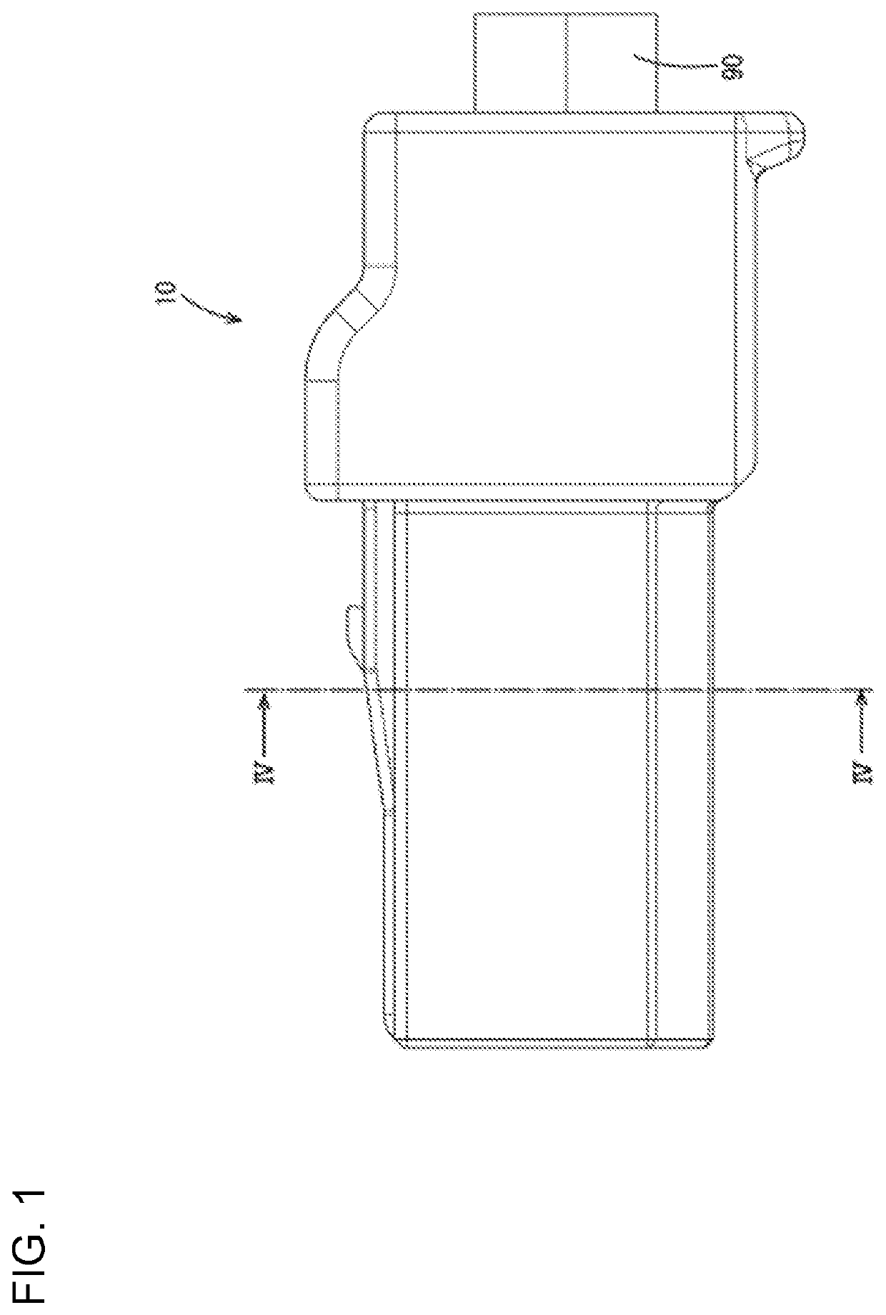
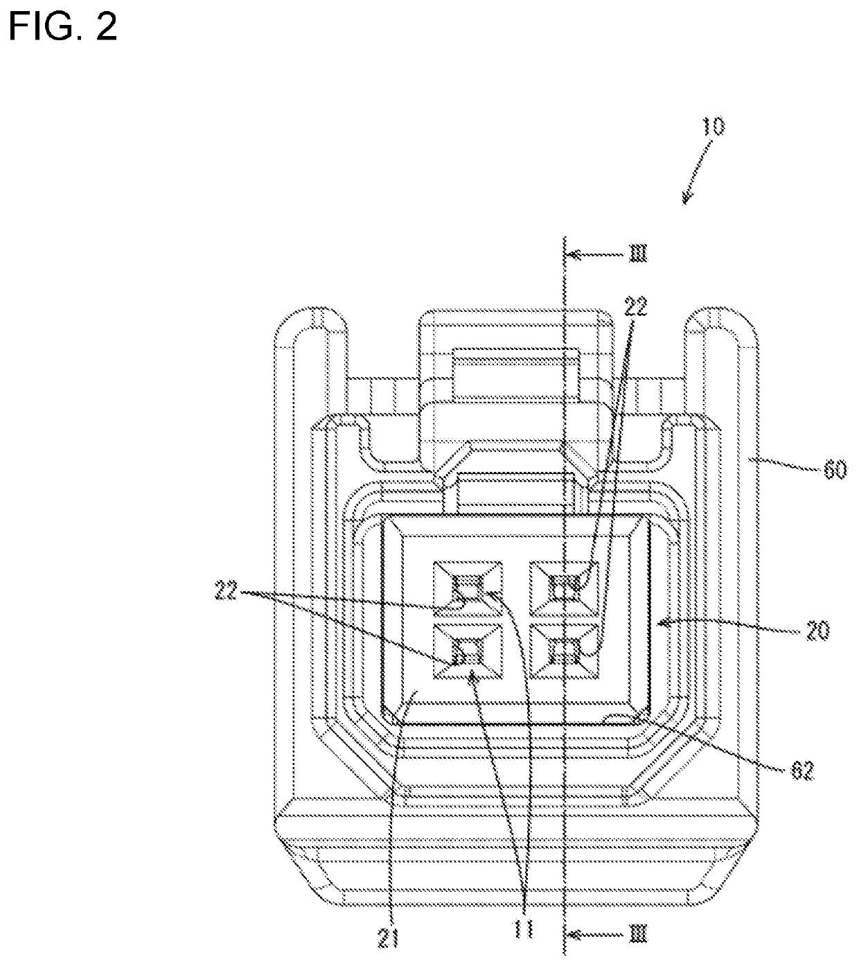
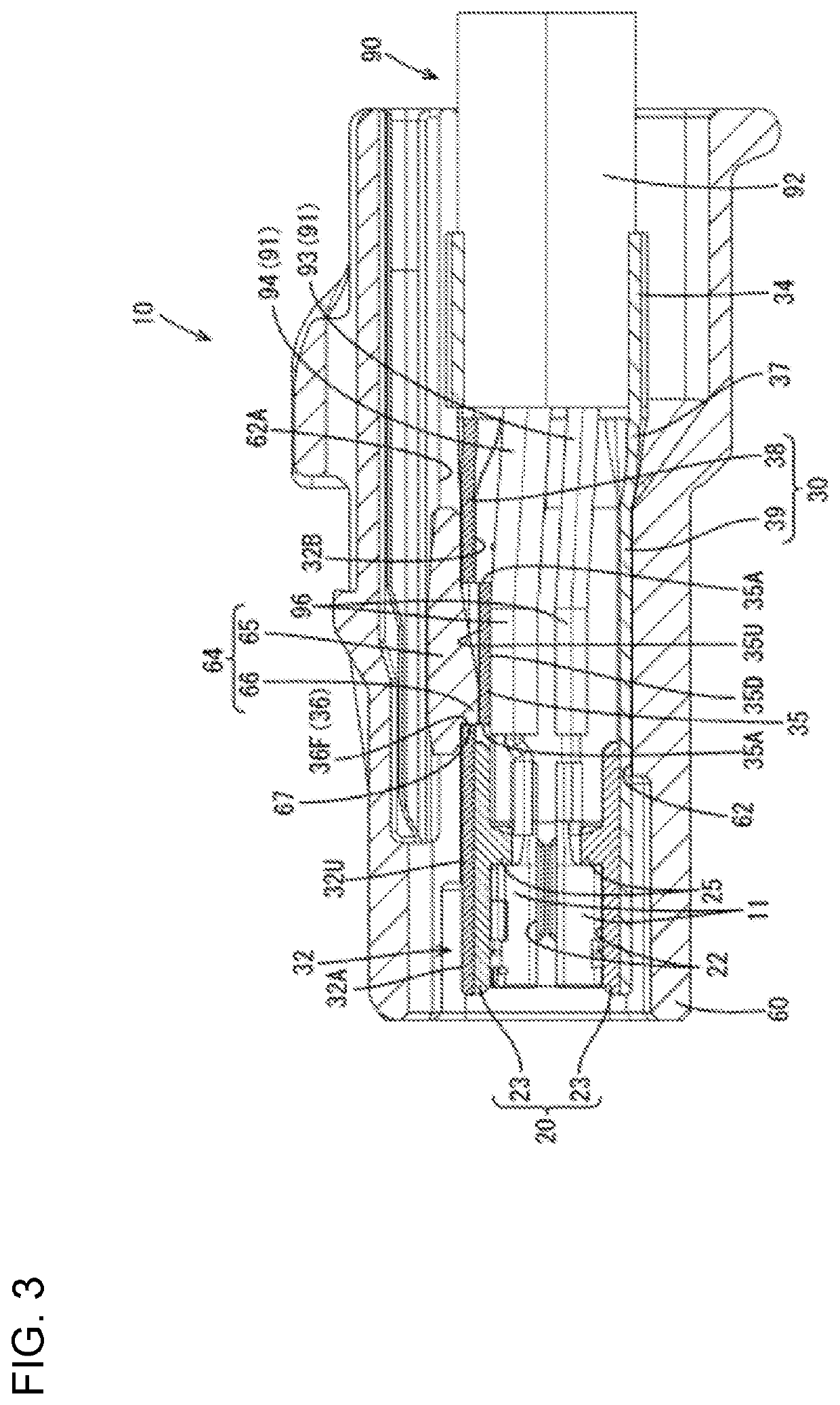
[0028]An embodiment of the disclosure is described with reference to FIGS. 1 to 9. This embodiment relates to a connector 10 for high-speed communication to be installed in a vehicle and illustrates the connector 10 to be connected to a front part of a cable 90 as shown in FIG. 1.

[0029][Cable 90]

[0030]As shown in FIGS. 1 and 3, the cable 90 extends in a front-rear direction. The cable 90 is formed by covering the outer peripheries of a plurality of wires 91 by an insulating outer coating 92. The cable 90 of this embodiment is formed by collectively covering four wires 91 by the outer coating 92. Each wire 91 is formed by covering a conductive core by an insulating...


PUM


Abstract

A connector (10) is to be connected to an end part of a cable (90). The cable (90) is formed by covering outer peripheries of at least two twisted wires (91) by an outer coating (92). The connector includes a conductive tubular portion (32) and an outer housing (60). The wires (91) are inserted into the tubular portion (32). The tubular portion (32) includes a suppressing portion (35) having an outer surface recessed from an outer surface of the tubular portion (32) and an inner surface projecting further toward the wires (91) than an inner surface of the tubular portion (32). The outer housing (60) includes an accommodating portion (62) for accommodating the tubular portion (32). The accommodating portion (62) includes a locking portion (66) to be fit into a recessed part of the suppressing portion (35) in an intersecting direction intersecting a withdrawing direction of the tubular portion (32).

Description

BACKGROUNDField of the Invention[0001]The disclosure relates to a connector.Related Art[0002]Japanese Unexamined Patent Publication No. 2017-204335 discloses a connector for high-speed communication to be connected to an end part of a twisted pair cable. The twisted pair cable is formed by surrounding the outer peripheries of two twisted signal wires by an outer member. The connector includes a tubular shell and an outer housing for accommodating the shell. End regions of the two signal wires are exposed from the outer member, untwisted and inserted into the tubular shell[0003]Impedance tends to increase in the parts of the signal wires of the twisted pair cable that are exposed from the outer member and untwisted. Thus, the shell is formed such that a rear part thereof is smaller than a front part for the purpose of suppressing an impedance increase. Further, an impedance adjusting portion is formed inside the rear part of the shell in proximity to the signal wires.[0004]Japanese U...

Claims


Application Information

Patent Timeline
IPC IPC(8): H01R13/506H01R13/6477
CPCH01R13/506H01R13/6477H01R13/6473H01R13/6463H01R13/502H01R13/42H01R13/65915
Inventor SAKAI, MASAMI
Owner SUMITOMO WIRING SYST LTD
Why Eureka
Try Eureka