Developing device and image forming apparatus

a technology of developing device and image forming apparatus, which is applied in the direction of electrographic process apparatus, instruments, optics, etc., can solve problems such as concentration differences

Active Publication Date: 2020-10-15
FUJIFILM BUSINESS INNOVATION CORP
View PDF0 Cites 0 Cited by
  • Summary
  • Abstract
  • Description
  • Claims
  • Application Information

AI Technical Summary

Benefits of technology

[0005]Aspects of non-limiting embodiments of the present disclosure relate to a developing device and an image forming apparatus that reduces a difference in concentration of a developer in an axial direction of a conveying member compared with a case where a rotation member that is rotated to allow the developer to pass through a space between a developer accumulating member and the rotation member is not provided.

Problems solved by technology

Here, when an amount of a developer changes in an axial direction of a conveying member during supply of the developer from the conveying member to a developer carrier, a supply amount of the developer varies in the axial direction and an amount of the developer on the developer carrier varies in the axial direction, which may cause a concentration difference.
However, aspects of the non-limiting embodiments are not required to address the advantages described above, and aspects of the non-limiting embodiments of the present disclosure may not address advantages described above.

Method used


Image

  • Developing device and image forming apparatus
  • Developing device and image forming apparatus
  • Developing device and image forming apparatus

Examples


Embodiment Construction

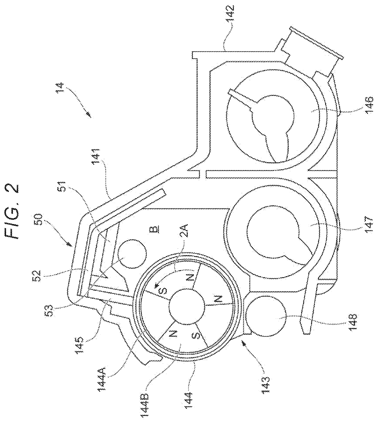
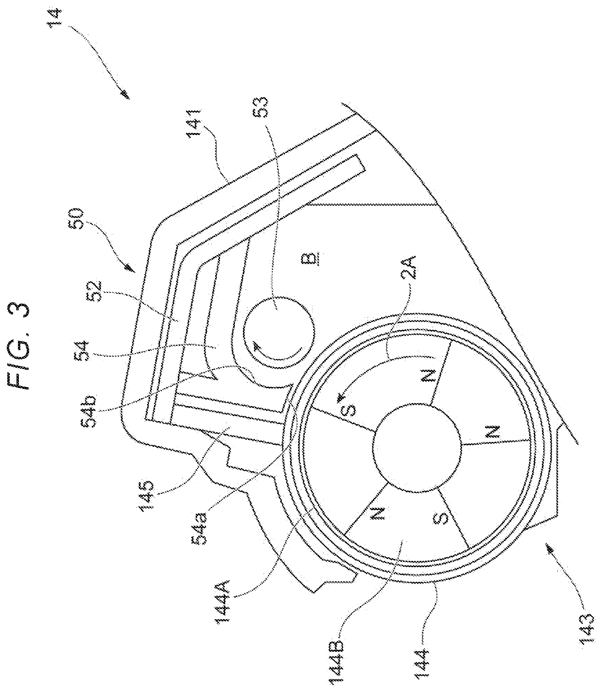
[0013]Hereinafter, exemplary embodiments of the present disclosure will be described in detail with reference to the accompanying drawings.

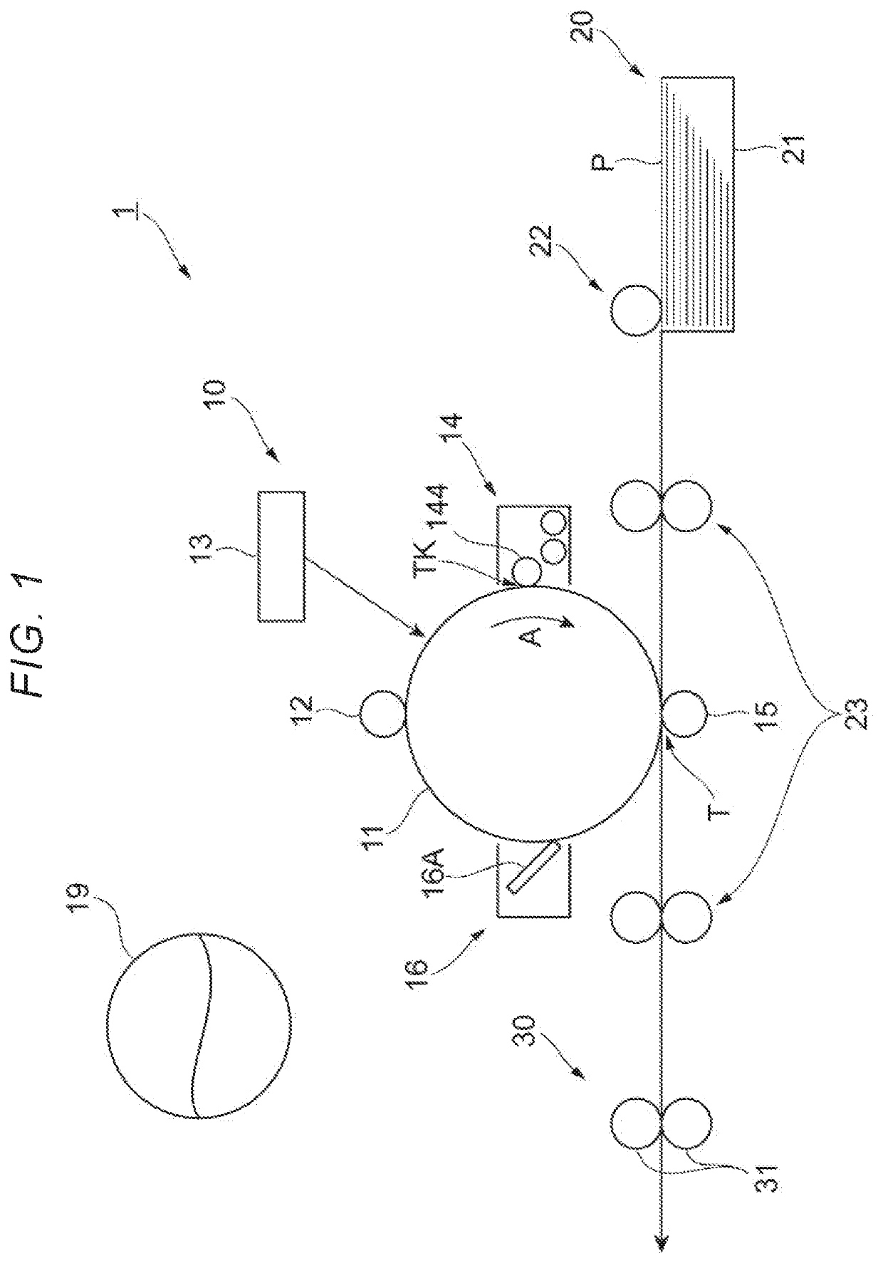
[0014]FIG. 1 is a view showing an overall configuration of an image forming apparatus 1. In addition, FIG. 1 is a view of the image forming apparatus 1 when viewed from a front side of the image forming apparatus 1.

[0015]The image foaming apparatus 1 includes an image forming unit 10, a paper feeding unit 20, and a fixing unit 30.

[0016]The image forming unit 10 forms a toner image on a paper P using an electrophotographic method. The paper P is an example of a recording material. The paper feeding unit 20 feeds the paper P to the image forming unit 10. The fixing unit 30 fixes, onto the paper P, an image, that is, the toner image formed on the paper P by the image forming unit 10.

[0017]The image forming unit 10 includes a photoconductor drum 11 that is rotated in a direction indicated by an arrow A. The image forming unit 10 further includes a ch...


PUM


Abstract

A developing device includes a developer carrier configured to carry a developer to be supplied to an image carrier on which an electrostatic latent image is to be formed, a conveying unit configured to convey the developer containing a toner and a carrier, a regulating member configured to regulate the developer carried by the developer carrier to a specified amount, a developer accumulating member disposed upstream of the regulating member in a rotation direction of the developer carrier, the developer accumulating member forming an accumulating portion in which the developer accumulates, and a rotation member disposed between the developer accumulating member and the developer carrier, the rotation member being rotated to allow the developer to pass through a space between the developer accumulating member and the rotation member.

Description

CROSS-REFERENCE TO RELATED APPLICATIONS[0001]This application is based on and claims priority under 35 USC 119 from Japanese Patent Application No. 2019-075602 filed Apr. 11, 2019.BACKGROUND(i) Technical Field[0002]The present disclosure relates to a developing device and an image forming apparatus.(ii) Related Art[0003]For example, JP-A-2-284162 discloses a configuration in which a picked up developer is made uniform in an axial direction by a conveying screw which faces a developing roller.SUMMARY[0004]Here, when an amount of a developer changes in an axial direction of a conveying member during supply of the developer from the conveying member to a developer carrier, a supply amount of the developer varies in the axial direction and an amount of the developer on the developer carrier varies in the axial direction, which may cause a concentration difference.[0005]Aspects of non-limiting embodiments of the present disclosure relate to a developing device and an image forming appara...

Claims


Application Information

Patent Timeline
Patent Type & Authority Applications(United States)
IPC IPC(8): G03G15/08
CPCG03G15/0812G03G15/081G03G15/0921
Inventor YOSHII, TOMOYUKI
Owner FUJIFILM BUSINESS INNOVATION CORP
Why Eureka
Try Eureka