Pipe coupling assembly

a technology of coupling assembly and pipe, which is applied in the direction of pipe-joints, textile cables, sleeves/socket joints, etc., can solve the problems of significant weight associated with each section, bell or outer pipe of the mating pipe section has a tendency to deflect away, and further weakened

Active Publication Date: 2020-10-22
SPRINGSEAL
View PDF2 Cites 0 Cited by
  • Summary
  • Abstract
  • Description
  • Claims
  • Application Information

AI Technical Summary

Benefits of technology

The present patent describes a locking mechanism for use with a coupler assembly for sealing pipe. The mechanism includes a partially hollow cylindrical body with separate cords paths connected at opposite ends. The body has tabs that flex into the cords paths to secure the pipe connection. The technical effect of this design is to provide a reliable and flexible locking mechanism for sealing pipe that ensures a secure and tight connection.

Problems solved by technology

Clay tile is typically constructed in one or two foot sections and possesses many inherent deficiencies, such as, susceptibility to cracking, labor-intensive installation in placement of the sections in close proximity, and the significant amount of weight associated with each section.
Additionally, the bell or outer pipe of the mating pipe sections has a tendency to deflect away from the elastomeric gasket during insertion.
The deflected area of the outer pipe or bell is often disposed to leaks and is further weakened with its exposure to fluid and / or fluid pressure.
The hinge-like motion becomes more pronounced in assisting aligning the pipe sections where precise alignment is difficult, because of the piping being partially buried in the ground.

Method used


Image

  • Pipe coupling assembly
  • Pipe coupling assembly
  • Pipe coupling assembly

Examples


Embodiment Construction

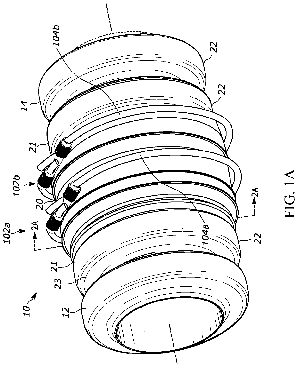
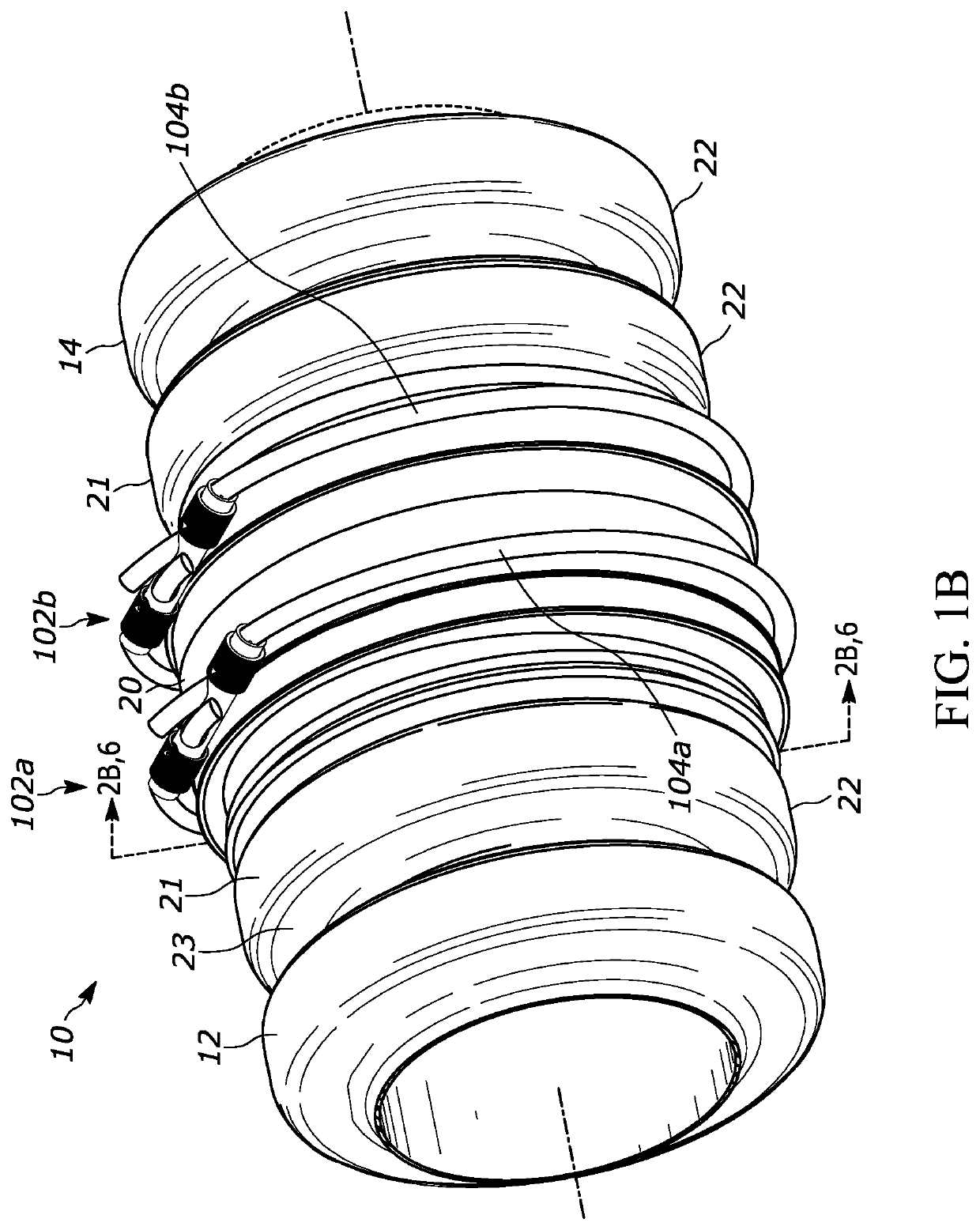
[0038]The present invention relates to a pipe coupling assembly for connecting two pieces of pipe or over an opening in a single pipe using a cord and locking mechanism, and more specifically, a pipe coupling assembly providing a fluid-tight connection between two pieces of piping or over an opening in a single pipe using a cord and locking mechanism.

[0039]Referring to the figures, and in particular FIGS. 1A-1B, which are perspective views of a pipe coupling assembly 10 constructed in accordance with one embodiment of the disclosure forming a fluid-tight sealing connection between first and second pipe sections 12, 14, respectively.

[0040]While the first and second pipe sections 12, 14 in FIGS. 1A-1B illustrate corrugated piping constructions, the pipe coupling assemblies of the present disclosure are used to couple other types of piping, including for example, polyvinyl chloride (PVC), straight metal piping, and the like without departing from the spirit and scope of the claimed dis...


PUM


Abstract

A locking mechanism for use with a coupler assembly for sealing pipe is described herein. The locking mechanism comprises a partially hollow cylindrical body having a first end opposite a second end along a common axis, the body defining a first cord path connecting the first end to a first arcuate opening defined in the body and a second cord path connecting the second end to a second arcuate opening defined in the body, wherein the first cord path and the second cord path comprise separate paths. The locking mechanism further comprising first and second caps that are slidably attachable to the first and second ends of the body, respectively and a cord having a first end portion located within the first cord path and a second end portion located within the second cord path.

Description

CROSS REFERENCE TO RELATED APPLICATION[0001]The present application is a non-provisional application that claims priority under 35 U.S.C. § 119(e) to co-pending U.S. Provisional Application Ser. No. 62 / 835,723 entitled PIPE COUPLING ASSEMBLY that was filed on Apr. 18, 2019 with the United States Patent Office, the present application claims priority to said provisional application which is incorporated by reference in its entirety herein for all purposes.TECHNICAL FIELD[0002]The present invention relates to a pipe coupling assembly for connecting two pieces of pipe or for positioning over an opening in a single pipe using a cord and locking mechanism, and more specifically, a pipe coupling assembly providing a fluid-tight connection between two pieces of piping or over an opening in a single pipe using a cord and locking mechanism.BACKGROUND[0003]It is desirable to form a fluid-tight seal between two pipe sections, including piping typically used for drainage, sanitary sewer applica...

Claims


Application Information

Patent Timeline
Patent Type & Authority Applications(United States)
IPC IPC(8): F16L21/08
CPCF16L21/08F16L25/0036F16L21/005F16G11/10
Inventor KNAPP, MARK
Owner SPRINGSEAL
Why Eureka
Try Eureka