
Under-display image sensor

a technology of image sensor and display screen, which is applied in the field of imaging systems and methods, can solve the problems of limiting the screen-to-body ratio of the device, unfavorable black border, etc., and achieve the effect of limiting the scope of the claimed subject matter

Active Publication Date: 2020-12-10
SYNAPTICS INC
View PDF0 Cites 16 Cited by
  • Summary
  • Abstract
  • Description
  • Claims
  • Application Information

AI Technical Summary

Benefits of technology

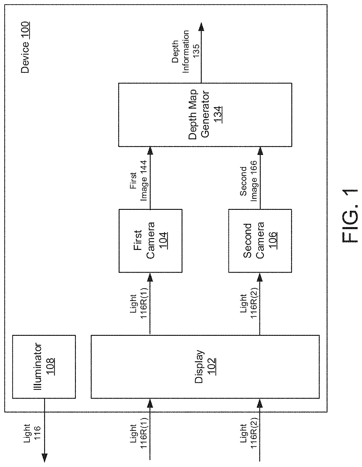
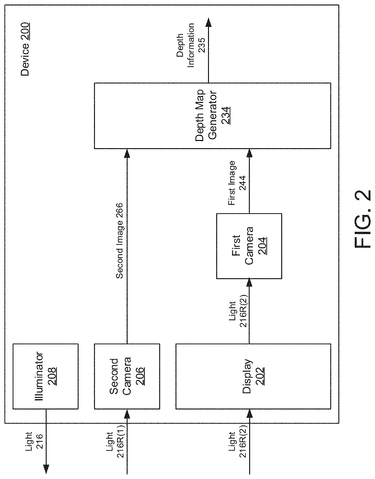
This patent describes a device that has a screen and a light source. There is also a camera behind the screen that can capture images of the light reflected on the screen. The device also has a second camera nearby that can capture a different image. The device also has a depth map generator that can create a 3D map of the objects in the first and second cameras' field of view.

Problems solved by technology

This often results in a large, unsightly black border around the display, which may detract from the device's appearance and limit the device's screen-to-body ratio.

Method used


Image

  • Under-display image sensor
  • Under-display image sensor
  • Under-display image sensor

Examples


Embodiment Construction

[0023]In the following description, numerous specific details are set forth such as examples of specific components, circuits, and processes to provide a thorough understanding of the present disclosure. The term “coupled” as used herein means connected directly to or connected through one or more intervening components or circuits. Also, in the following description and for purposes of explanation, specific nomenclature is set forth to provide a thorough understanding of the aspects of the disclosure. However, it will be apparent to one skilled in the art that these specific details may not be required to practice the example embodiments. In other instances, well-known circuits and devices are shown in block diagram form to avoid obscuring the present disclosure. Some portions of the detailed descriptions which follow are presented in terms of procedures, logic blocks, processing and other symbolic representations of operations on data bits within a computer memory. The interconnec...


PUM


Abstract

A device includes a display and a first light source configured to emit light, wherein the first light source is proximate to the display. The device further includes a first camera disposed behind the display, wherein the first camera is configured to detect reflections of the light emitted by the first light source. The first camera is further configured to capture a first image based at least in part on the reflections, wherein the reflections are partially occluded by the display. The device also includes a second camera proximate to the display, wherein the second camera is configured to capture a second image. In addition, the device includes a depth map generator configured to generate depth information about one or more objects in a field-of-view (FOV) of the first and second cameras based at least in part on the first and second images.

Description

CROSS-REFERENCE TO RELATED APPLICATION[0001]This application claims the benefit of co-pending and commonly owned U.S. Provisional Patent Application No. 62 / 857,740 entitled “UNDER-DISPLAY IMAGE SENSOR,” filed on Jun. 5, 2019, the entirety of which is hereby incorporated by reference.TECHNICAL FIELD[0002]The present embodiments relate generally to systems and methods for imaging, and specifically to under-display image sensors.BACKGROUND OF RELATED ART[0003]Many electronic devices such as smartphones, tablets, laptops and other computing systems include a camera and display. The camera is often disposed within a region of the device that provides an unobstructed view of the environment. Thus, when integrated on the same surface as the display, the camera is often disposed adjacent to the display, within a notch or cutout. This often results in a large, unsightly black border around the display, which may detract from the device's appearance and limit the device's screen-to-body ratio...

Claims


Application Information

Patent Timeline
Patent Type & Authority Applications(United States)
IPC IPC(8): H04N5/225H04N13/254
CPCH04N5/2257H04N13/254H04N5/2256H04N13/239H04N13/271H04N5/2226H04N2013/0081H04N23/56H04N23/57H04N23/45H04N23/90
Inventor GOVE, ROBERT J.
Owner SYNAPTICS INC
Features
  • Generate Ideas
  • Intellectual Property
  • Life Sciences
  • Materials
  • Tech Scout
  • Unparalleled Data Quality
  • Higher Quality Content
  • 60% Fewer Hallucinations
Learn More