
Built-In Air Pump Assembly

a built-in air pump and assembly technology, applied in the field of air pumps, can solve the problems of increased cost and reliability, many drawbacks of the existing built-in air pump, and the inability to meet the needs of the customer,

Active Publication Date: 2020-12-17
SUN PLEASURE
View PDF0 Cites 0 Cited by
  • Summary
  • Abstract
  • Description
  • Claims
  • Application Information

AI Technical Summary

Benefits of technology

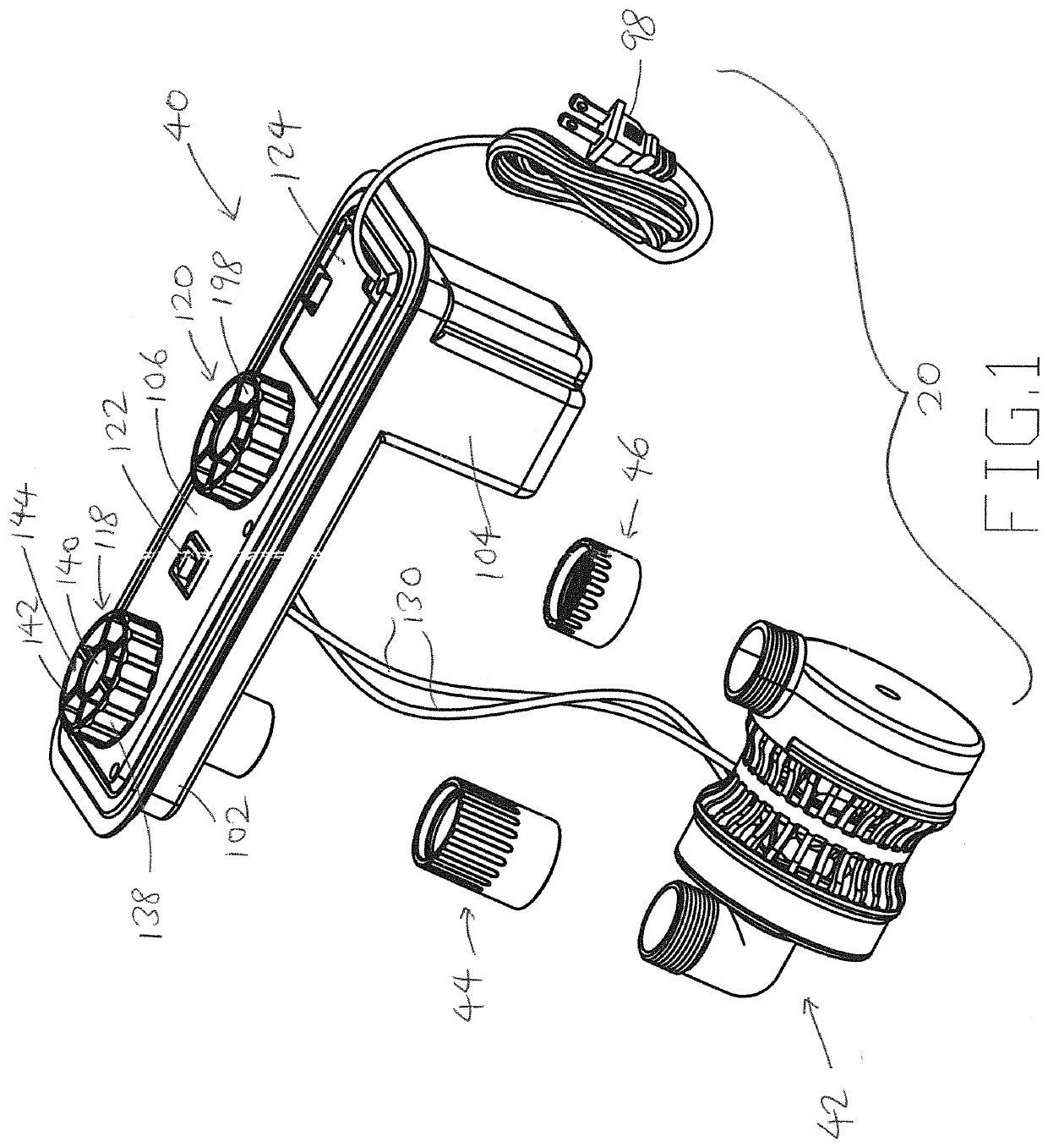
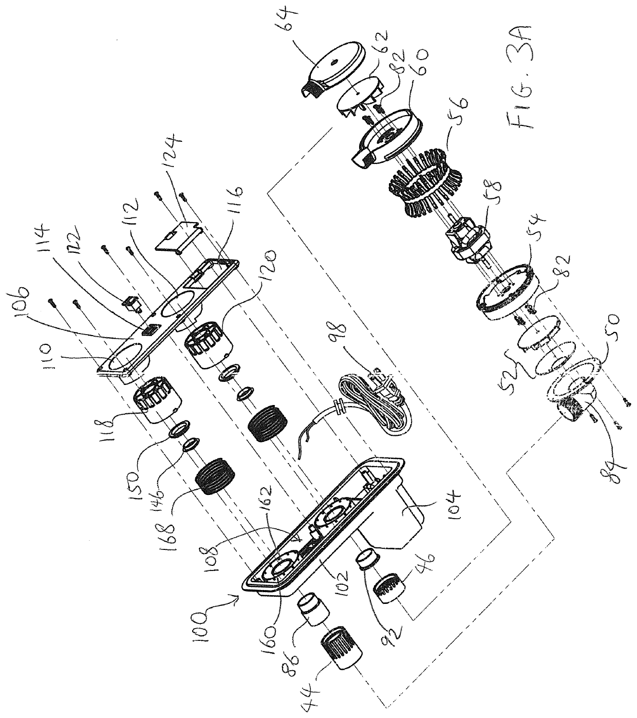
The pump assembly described in this patent allows for quick delivery of air into and out of a device. It includes a double-blower assembly with a motor that is supported between two blowers. This design allows for quick air exchange, with air coming in quickly and spreading out quickly around the motor. It also allows for quick air exhaust, with air coming in from all over the device. The design can even be without a net to reduce obstruction in the air flow. Overall, this pump assembly provides improved air delivery and exchange for devices.

Problems solved by technology

Many of the existing built-in air pumps suffer from a number of drawbacks.
For example, the construction of these built-in air pumps can be complicated which leads to increased cost and reliability issues.
In addition, many of the existing pump units have their vents exposed to the environment when the product is either inflated in use or deflated for storage (i.e., when the pump unit is not in use), so that the interior of the pump units can be contaminated by water or dirt.
These pumps have complicated air passages and many components that must be structurally matched, which often leads to large airflow loss and high air leakage during the inflation process.
At the same time, the complicated structure also increases the difficulties and costs of production.

Method used


Image

  • Built-In Air Pump Assembly
  • Built-In Air Pump Assembly
  • Built-In Air Pump Assembly

Examples


first alternative embodiment

[0056]FIGS. 9-10 illustrate another embodiment of the present invention. The embodiment in FIGS. 9-10 is the same as the embodiment in FIGS. 1-7, except that the knobs 118 and 120 are now replaced by screw caps 1118 and 1120. Otherwise, all the other elements that are the same as those in the embodiment of FIGS. 1-7 have the same numeral designations.

[0057]In the embodiment of FIGS. 9-10, the springs 168 are now omitted as they are unnecessary. Each screw cap 1118 and 1120 has a generally cylindrical ledge 1122 with a curved slot 1124 cut out of a portion of the ledge 1122. The curved slot 1124 is adapted to receive a curved ridge (not shown) extending from the base 1126 of the rectangular section 102. The ledge 1122 surrounds the cylindrical wall 162 or 192 when the screw cap 1118 or 1120 is screwed tight to shut the air channels 180 and 194. The inflate / deflate operations of this embodiment are identical to the inflate / deflate operations of the embodiment in FIGS. 1-7.

[0058]Benefi...

second alternative embodiment

[0063]FIGS. 11-15 illustrate another embodiment of the present invention. The embodiment in FIGS. 11-15 is the same as the embodiment in FIGS. 1-8B, except that the double-blower assembly has been replaced by a double-blower double-motor assembly 42. The control housing assembly 40 can be the same as for FIGS. 1-8B, and the same numerals are used in FIGS. 1-8B and 11-14 to represent the same elements. In addition, a battery assembly 220 can be housed inside a battery housing 222 that is secured inside the storage section 104. A DC plug 224 can be electrically coupled to the battery housing 222 and the control button 122. A separate charging assembly 228 can be provided for charging the battery assembly 220.

[0064]The double-blower double-motor assembly 1042 has a housing frame 230 that supports two motors 232 and 234, and two blowers 242 and 244 that are coupled to the motors 232 and 234, respectively, via shafts 282 and 292, respectively. A blower 242 is oriented horizontally on a f...

third alternative embodiment

[0070]FIG. 16 illustrates another embodiment of the present invention. The embodiment in FIG. 16 is the same as the embodiment in FIGS. 11-15, except that the single housing frame 230 and lower housing 280 is replaced by separate housings 302 and 304, each for housing a separate set of blowers and motors. With the locations and orientations of the openings 270 and 290 remaining the same as in FIGS. 11-14, the orientations and locations for the blowers and motors in the housings 302 and 304 can be similar to those in FIGS. 11-14.

[0071]FIG. 17 illustrates a modification that can be made to the embodiment in FIG. 16, where the openings 270 and 290 are provided at different locations and orientations.


PUM


Abstract

A pump assembly is provided for use with an inflatable product. The inflatable product has a chamber having an air inlet and an air outlet. The pump assembly has a pump unit that is positioned inside the chamber for inflating and deflating the chamber, the pump unit having at least one motor that is operatively coupled to a first blower and a second blower, with the first blower fluidly coupled to the air inlet and the second blower fluidly coupled to the air outlet. The chamber is inflated by intake of air through the air inlet to the first blower and then into the chamber, and the chamber is deflated by drawing air from the chamber to the second blower and then out of the chamber through the air outlet.

Description

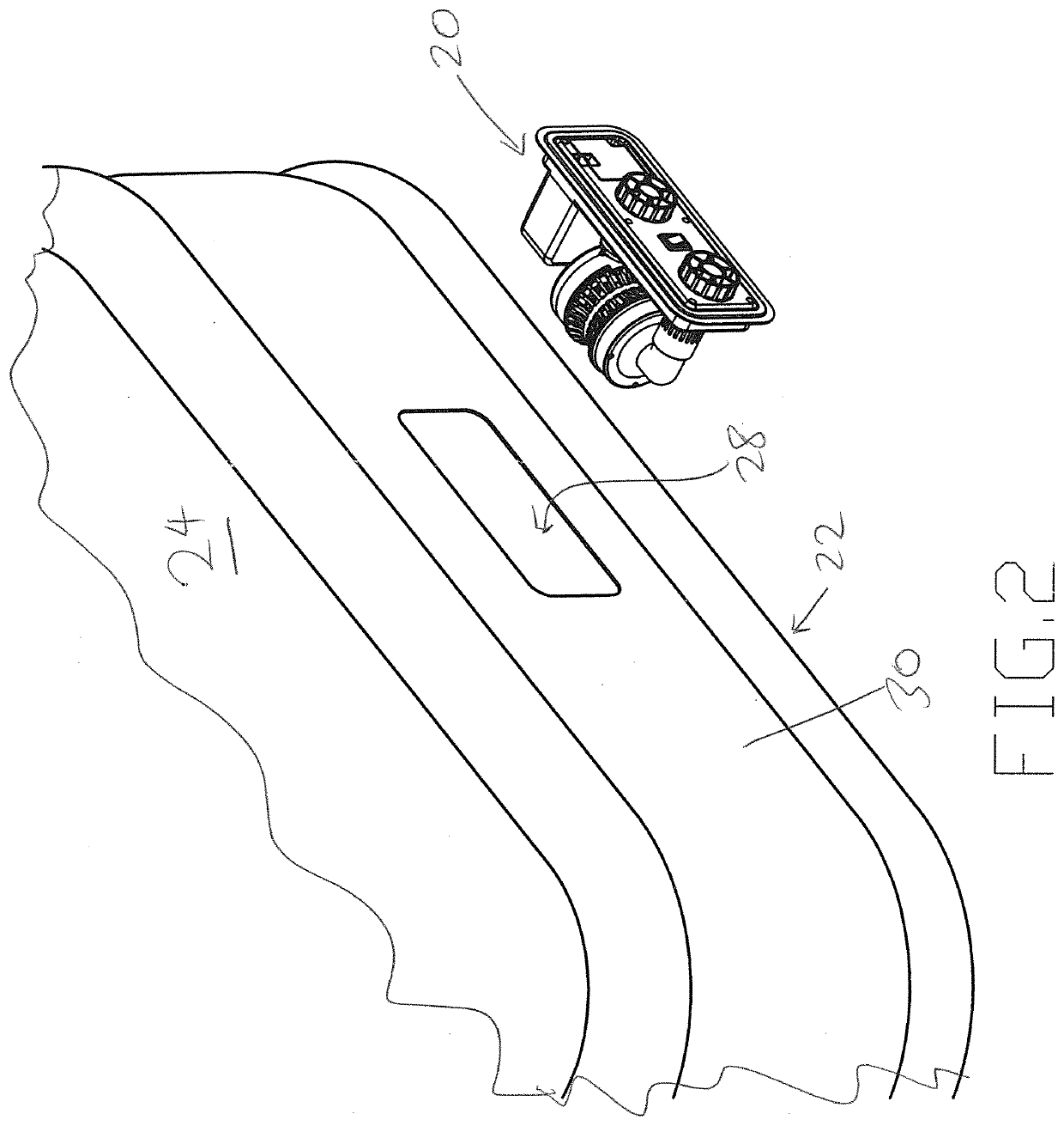
BACKGROUND OF THE INVENTION1. Field of the Invention[0001]The present invention relates to air pumps, and more particularly to a built-in air pump that can be deployed for inflation and deflation of an inflatable product, such as an air mattress.2. Description of the Prior Art[0002]Inflatable products have become very popular. In particular, inflatable air mattresses have become a very useful item that has found use at homes, camping and other applications. These inflatable air mattresses are typically inflated and deflated by air pumps. Some of these mattresses have been provided with built-in air pumps that can be stored in a socket or space that is provided in the housing of the mattress, and then pulled out and deployed for use in inflating and deflating the mattress.[0003]Many of the existing built-in air pumps suffer from a number of drawbacks. For example, the construction of these built-in air pumps can be complicated which leads to increased cost and reliability issues. In ...

Claims


Application Information

Patent Timeline
Patent Type & Authority Applications(United States)
IPC IPC(8): F04D25/16A47C27/08F04D25/06
CPCA47C27/082F04D25/06F04D25/16F05B2260/602F04D25/08F04D29/403F04D25/084F04D29/4253F04D17/164F04D25/166F04D25/0606F04D25/068
Inventor LAU, VINCENT W.S.LONG, SHOUGUO
Owner SUN PLEASURE
Learn More