Vehicle Flooring System

a technology for vehicles and flooring, applied in vehicle arrangements, superstructure connections, transportation and packaging, etc., can solve the problem of low skill labor required to install systems, and achieve the effect of optimizing system strength and optimal spacing

Active Publication Date: 2017-02-23
VALEDA
View PDF0 Cites 2 Cited by
  • Summary
  • Abstract
  • Description
  • Claims
  • Application Information

AI Technical Summary

Benefits of technology

[0041]Adhesive windows 36, 46 are provided on the registration plates 30, 40 in the areas that contact the floor ribs 4 of the vehicle, thus allowing direct bonding between the ribs 4 and the floor extrusion planks 20 and optimizing the strength of the system.
[0042]Central ports 37, 47 are added to all the contact tabs 31, 41 that are bonded to the vehicle floor valleys 6 located between the ribs 4. The tabs 31, 41 are designed to avoid direct contact with the valleys 6 and maintain optimal spacing of roughly 1.5 mm for the adhesive layer. The central ports 37, 47 can be used to inject adhesive with the applicator nozzle so that it propagates outward in the event that insufficient amounts of adhesive were applied prior to positioning. Lastly, the central ports 37, 47 provide a path for moisture in the ambient air to react with the adhesive.
[0043]Stand-offs 38, 48 are strategically located to elevate the floor extrusion planks 20 from the registration plates 30, 40 and to provide minimal required adhesive between the mating surfaces. The stand-offs 38, 48 were introduced to the design so that they take advantage of the existing forming operations and require no secondary operations.

Problems solved by technology

Only low skill labor is required to install the system.

Method used


Image

  • Vehicle Flooring System
  • Vehicle Flooring System
  • Vehicle Flooring System

Examples


Embodiment Construction

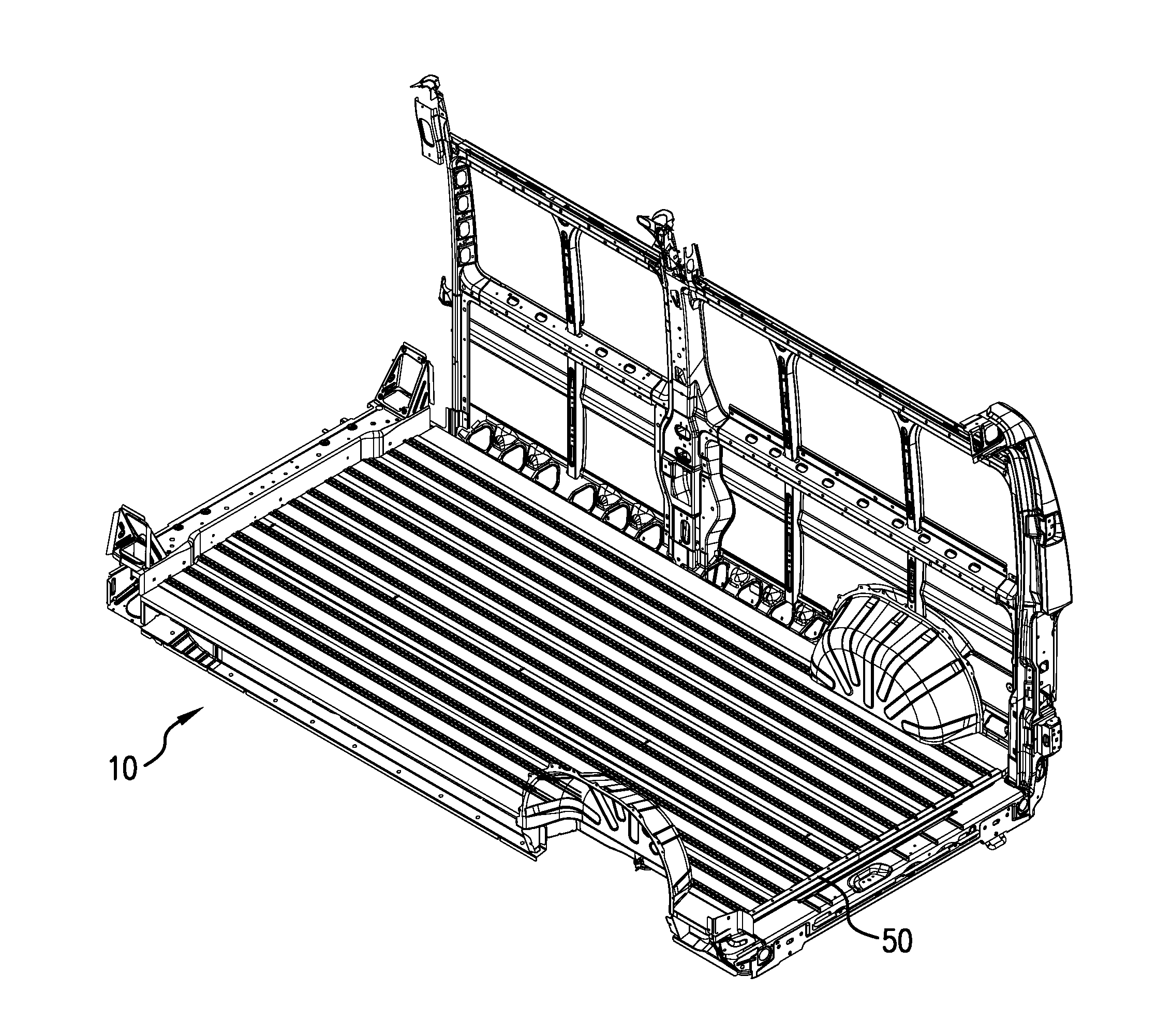
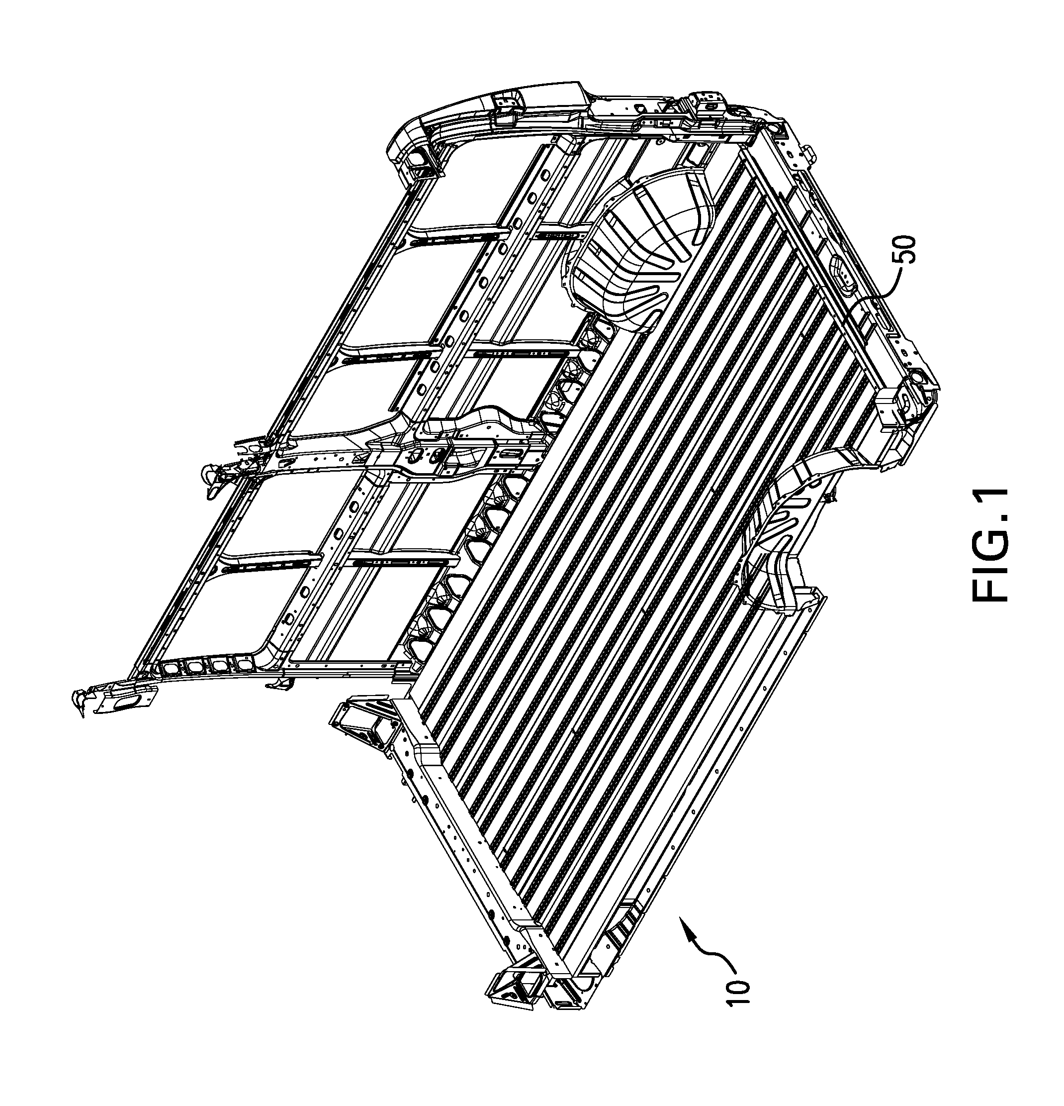
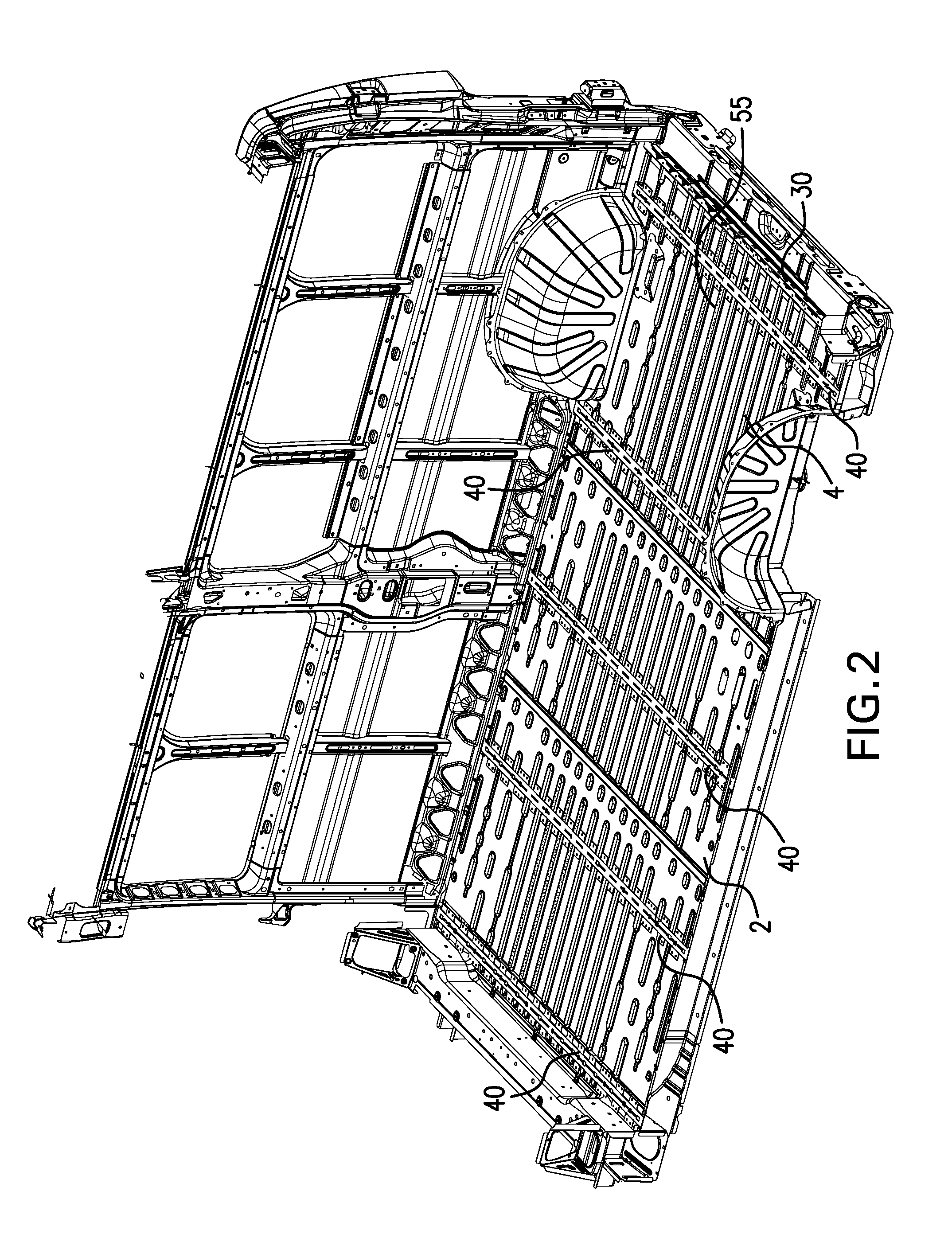
[0029]In a first embodiment shown in FIGS. 1-9 and 11-12, a floor system 10 for a vehicle floor may comprise a plurality of floor panels (or planks) 20, a plurality of registration plates (including a rear registration plate 30 and / or one or more standard registration plates 40), a load-bearing sill 50, a plurality of load spreader plates 60, and various adhesive materials and fasteners. A typical installation of the floor system 10 is described below:

[0030]Step 1: The van floor 2 is exposed to reveal metal corrugations. Loose debris should be removed and the floor 2 should be cleaned with a non-residue forming alcohol-based solvent.

[0031]Step 2: The rear registration plate 30 depicted in FIGS. 4-6 should be installed on the van floor 2 at the rear of the van using the following method:[0032]a. Dry fit and check alignment of the rear registration plate 30. The large tabs (or support members) 31 are configured to sit between corrugated ribs 4 on the vehicle floor 2.[0033]b. Bend regi...


PUM


Abstract

A flooring system for a vehicle having a corrugated floor comprises a plurality of flooring panels supported at their undersides by two or more registration members having locating members and other features for aligning the flooring panels vertically, laterally, and longitudinally. The flooring panels each have at least one longitudinally aligned load-bearing structure, such as in integrated track or a universal channel configured to receive a flanged track, filler material, or both. The registration members may have depending support members configured to engage in the valleys of the corrugated vehicle floor.

Description

CROSS-REFERENCE TO RELATED APPLICATIONS[0001]This application claims priority to U.S. Patent Application No. 62 / 200,210, which is incorporated herein in its entirety by reference.STATEMENT REGARDING FEDERALLY SPONSORED RESEARCH OR DEVELOPMENT[0002]Not Applicable.THE NAMES OF PARTIES TO A JOINT RESEARCH AGREEMENT[0003]Not Applicable.INCORPORATION-BY-REFERENCE OF MATERIAL SUBMITTED ON A COMPACT DISC[0004]Not Applicable.BACKGROUND[0005]Technical Field[0006]The embodiments described and claimed herein relate generally to a floor system of adequate strength for securing wheelchairs, chairs, and / or other cargo, that can be easily and quickly installed into existing vehicles, such as a van, by a single installer.[0007]Background Art[0008]U.S. Pat. No. 6, 595,142 (“the '142 patent”) discloses a floor system for a vehicle that is composed of a plurality of parallel substantially plane pipe profiles. Installing the floor system of the '142 patent in a vehicle involves, first, creating a floor...

Claims


Application Information

Patent Timeline
Patent Type & Authority Applications(United States)
IPC IPC(8): B62D25/20B62D27/02
CPCB62D27/023B62D25/2054A61G3/0808B60N2/01558
Inventor SLEVINSKY, PAUL EDWARDIMBRIGIOTTA, ROBERT ANTHONY
Owner VALEDA
Why Eureka
Try Eureka