
Circumferential matrix band

a matrix band and circumferential technology, applied in the direction of dental aids, etc., can solve the problems of restricted restoration procedure and source of interference to the dentist, and achieve the effects of less obstruction, easy tensioning, and less obstruction

Active Publication Date: 2018-01-30
DENTSPLY SIRONA INC
View PDF22 Cites 2 Cited by
  • Summary
  • Abstract
  • Description
  • Claims
  • Application Information

AI Technical Summary

Benefits of technology

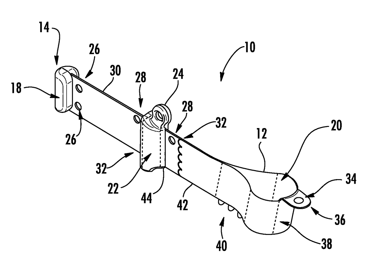
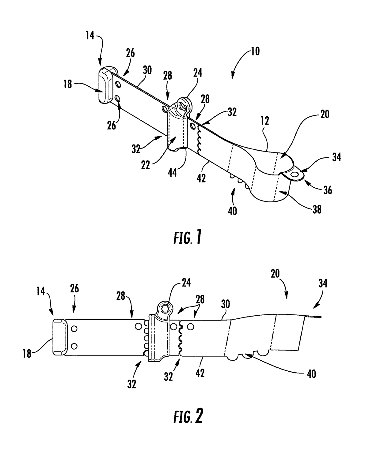
The present invention provides a dental matrix band that is easy to tension and offers less obstruction in the restoration area. The band includes a folded over band with two ends, one of which secures a stationary toggle and the other of which slides a movable toggle to adjust the size of the band. The band also has perforations for detachable band portions, holes for manipulation, and a top tab for easy removal. The invention enhances the dental restoration process by allowing for easier placement and tightening of the band, as well as providing better access for wedges to ensure secure contact with the tooth.

Problems solved by technology

The main problem with the prior art is that circumferential bands either require tensioners to be left in place during the restoration procedure to retain the tension on the matrix band, or the band is tensioned into a barrel-type feature.
In both cases the restoration procedure is restricted by the presence of the tensioning device.
As suggested above, the problem with the prior art is that matrix band retainers are left attached to the circumferential band during the restoration and are a source of interference to the dentist.

Method used


Image

  • Circumferential matrix band
  • Circumferential matrix band
  • Circumferential matrix band

Examples


Embodiment Construction

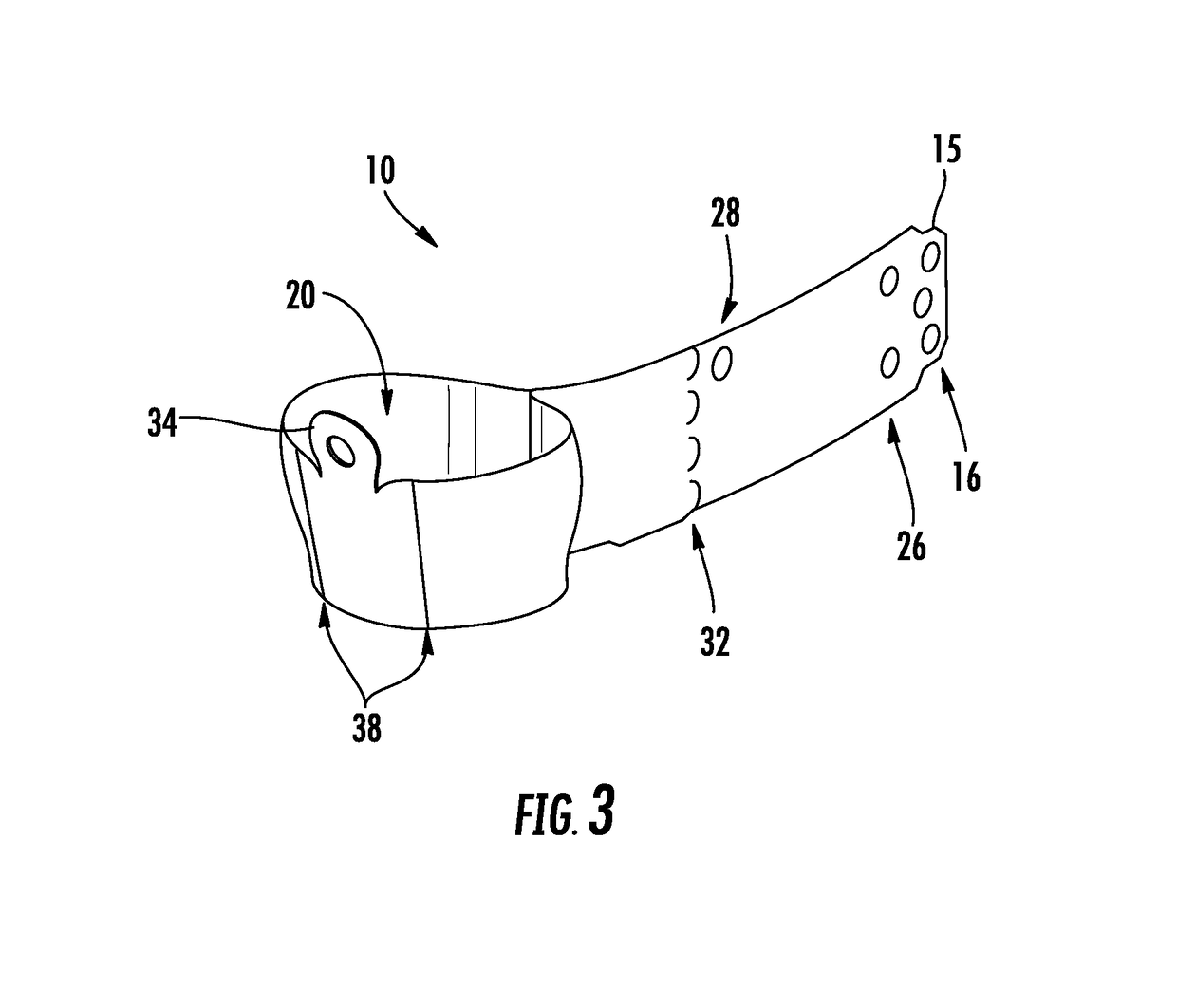
[0014]FIGS. 1 and 2 show a first embodiment of the circumferential dental matrix band 10 of the present invention. The circumferential dental matrix band 10 is shown to include a generally elongated metal band 12 having two ends 14. The ends 14 may include a tab portion 15 (see FIG. 3). One of more holes 16 (see FIG. 3) are provided at each of the ends 14. The elongated band 12 is folded back on its self so that the ends 14 meet and the respective one or more holes 16 are aligned. In this configuration, a first toggle 18 is molded over the ends 14 of the elongated band 12 and within the one or more holes 16. The ends 14 are thus secured in place and form a looped band 20 defining a circumference. A second toggle 22 is molded over the matrix band 10. However, the second toggle 22 is not molded within or through any holes in the matrix band 10. Rather, the second toggle 22 is molded in a manner to allow the second toggle 22 to slide along the matrix band 10. One embodiment considers a...


PUM


Abstract

A dental matrix band includes a band having a first end and a second end. The band is folded over with the first end and second end generally aligned. A portion of the band adjacent the first and second ends form opposed facing band portions in contact with one another, and another portion of the band forming a looped band forming a circumference. A first or stationary toggle is secured to the band at the first and second ends with the first toggle stationary with respect to the band. A second or movable toggle is formed over the band and is capable of sliding over the opposed facing band portions in contact with one another, whereby sliding of the movable toggle away from the first and second ends causes the circumference of the looped band to reduce in size.

Description

CROSS-REFERENCE TO RELATED APPLICATIONS[0001]This application claims the priority to New Zealand Application No. 593353, filed Jun. 9, 2011, New Zealand Application No. 595654, filed Oct. 10, 2011, and New Zealand Application No. 596177, filed Nov. 3, 2011, the entire contents of which all are hereby incorporated by reference.FIELD OF THE INVENTION[0002]The present invention relates to a dental matrix band, and in particular, a circumferential dental matrix band for use in restoring a tooth.BACKGROUND OF THE INVENTION[0003]Circumferential matrix bands and the use of matrix bands are well known and widely utilized in restorative dentistry.[0004]The main problem with the prior art is that circumferential bands either require tensioners to be left in place during the restoration procedure to retain the tension on the matrix band, or the band is tensioned into a barrel-type feature. In both cases the restoration procedure is restricted by the presence of the tensioning device.[0005]A de...

Claims


Application Information

Patent Timeline
Patent Type & Authority Patents(United States)
IPC IPC(8): A61C5/85
CPCA61C5/85
Inventor MCDONALD, SIMON P.
Owner DENTSPLY SIRONA INC
Learn More