A dual directional log-periodic antenna and an antenna arrangement

a log-period antenna and dual-directional technology, applied in the field of antennas, can solve the problems of considerable space saving of dual-directional antennas compared to two, and achieve the effect of saving considerable spa

Active Publication Date: 2020-12-17
SAAB AB
View PDF0 Cites 2 Cited by
  • Summary
  • Abstract
  • Description
  • Claims
  • Application Information

AI Technical Summary

Benefits of technology

[0022]In yet another example, the antenna is designed to operate between 0.15 GHz and 1.0 GHz. An advantage is that considerable space is saved by using a dual directional antenna in this frequency spectrum. The space saved along the transmission axis is approximately 15% to 20% compared to having two separate antennas. This is very valuable when the antennas mounted to a vehicle.
[0023]Further, the invention relates to an antenna arrangement. The antenna arrangement comprises an elongated member and first and second antennas. Each of the antennas is attached to a respective surface along the elongated member. Each respective surface is arranged to constitute at least part of the ground plane for the first and second antennas, respectively. The antenna elements are protruding away from the respective surface, such that the transmission axes of the first and second antennas are parallel to each other and such that the antenna elements of the first antenna are protruding in a direction inclined to the antenna elements of the second antenna. An advantage is that arbitrary polarisation states can be obtained in the main beam directions (along the transmission axis) when combining the two dual directional antennas.
[0024]In one example, the first port of the respective antenna are connected to each other via a first 180° hybrid, such that each respective first port can be operated either in phase or 180° out of phase, and the second port of the respective antenna are connected to each other via a second 180° hybrid, such that each respective second port can be operated either in phase or 180° out of phase. Thus four different types of patterns are obtained. An advantage is that these patterns can be combined and compared to each other for passive direction finding purposes. By amplitude comparisons, unwanted signals can be blocked and only measurements in the angular range giving uniqueness allowed. The prerequisite is that polarisation discrimination can be made, e.g. linear vertical, linear horizontal or circular. Another advantage is that the system also can be used for polarization matched jamming (linear vertical or horizontal) given that some polarization discrimination can be made.

Problems solved by technology

The dual directional antenna saves considerable space compared to two separate single directional antennas.

Method used


Image

  • A dual directional log-periodic antenna and an antenna arrangement
  • A dual directional log-periodic antenna and an antenna arrangement
  • A dual directional log-periodic antenna and an antenna arrangement

Examples


Embodiment Construction

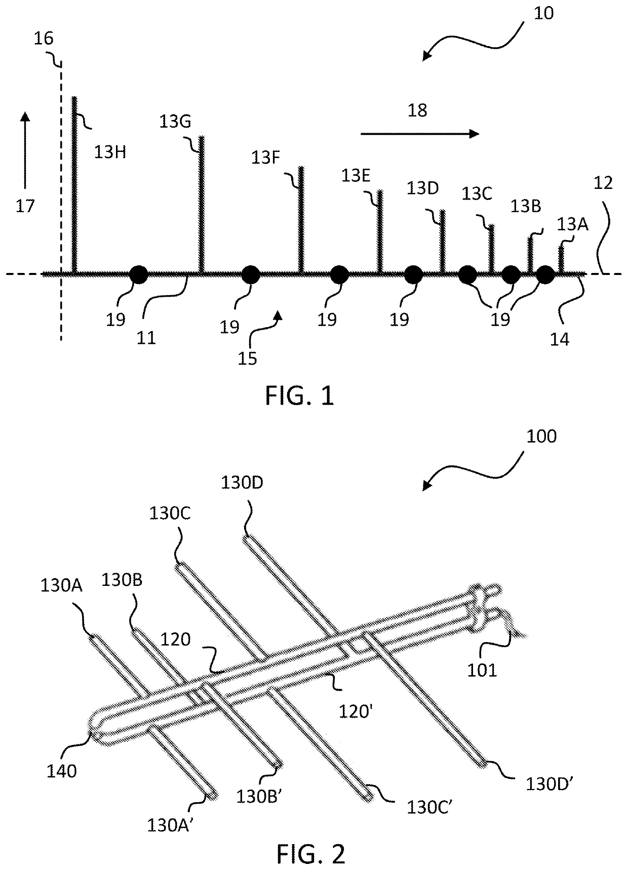
[0046]In this disclosure the term “antenna” includes the terms “antenna array” and “array”. FIG. 1 illustrates a schematic drawing of a log-periodic monopole antenna 10 according to prior art. The antenna 10 comprises a feed line 11 having first and second ends on opposite sides of the feed line 11. A transmission axis 12 is defined as the axis extending between the first and second ends of the feed line 11. Further, the antenna 10 comprises a plurality of antenna elements 13A, 13B, 13C, 13D, 13E, 13F, 13G, 13H arranged along the feed line 11, protruding from the transmission axis 12. The antenna 10 also comprises a port 14 at the first end of the feed line 11, wherein a part 15 of the antenna 10, from the port towards a reference point 16 along the transmission axis 12, comprises antenna elements 13A-H of gradually increasing length, in a direction 17 perpendicular to the transmission axis 12, and gradually increasing mutual distance between two consecutive antenna elements 13A-13B...


PUM


Abstract

The invention relates to an antenna. The antenna comprises a feed line having first and second ends on opposite sides of the feed line, wherein a transmission axis is defined as the axis extending between the first and second ends of the feed line. Further, the antenna comprises a plurality of antenna elements arranged along the feed line, protruding from the transmission axis. The antenna also comprises a first port at the first end of the feed line, wherein, at a first part of the antenna, the feed line, from the first port towards a reference point along the transmission axis, comprises antenna elements of gradually increasing length, configured to radiate in a first direction along the transmission axis from the reference point towards the first port during excitation in the first port. Yet further, the antenna comprises a second port at the second end of the feed line, wherein, at a second part of the antenna, the feed line, from the second port towards the reference point along the transmission axis, comprises antenna elements of gradually increasing length, configured to radiate in a second direction along the transmission axis from the reference point towards the second port during excitation in the second port.

Description

TECHNICAL FIELD[0001]The present disclosure relates to an antenna. Further, the present disclosure relates to an antenna arrangement.BACKGROUND ART[0002]A log-periodic antenna is partly defined in the following: If an antenna is mapped onto itself given a scaling of the dimensions with a factor 1 / τ, it obtains the same antenna characteristics at frequencies f and τ*f. Antenna characteristics become periodic with respect to the logarithm of the frequency and the period will be |log(τ)|. Antennas designed using these principles are called “log-periodic” antennas. The scaling condition described is a condition necessary but not sufficient to obtain log-periodically varying antenna characteristics. In reality, no antennas are truly “log-periodic”. A real antenna is of course truncated at the “large size end” and “small size end”, which results in bandwidth limitations. The large size end determines the lower frequency limit and the small size end (usually located near the feed point) de...

Claims


Application Information

Patent Timeline
Patent Type & Authority Applications(United States)
IPC IPC(8): H01Q11/10H01Q21/24
CPCH01Q21/24H01Q11/10H01Q21/245H01Q19/10H01Q9/36H01Q9/42H01Q5/25
Inventor FORSLUND, OLA
Owner SAAB AB
Why Eureka
Try Eureka