Connector, connector position assurance member and wiring harness

Active Publication Date: 2020-12-31
SUMITOMO WIRING SYST LTD
View PDF0 Cites 3 Cited by
  • Summary
  • Abstract
  • Description
  • Claims
  • Application Information

AI Technical Summary

Benefits of technology

[0013]Accordingly, the inclined surface inclined down or in toward the end part on the side of the body is formed on the upper surface of the inserting portion. Specifically, a part of the inserting portion to be inserted first between the upper surface of the receptacle and the lower surface of the connection releasing portion is formed on the inclined surface. In this way, the contact of the inserting portion with the connection releasing portion can be suppressed when inserting the inserting portion between the upper surface of the receptacle and the lower surface of the connection releasing portion. As a result, an unintended displacement of the connection releasing portion is suppressed.
[0014]The connector position assurance member may further include an operating portion (particularly substantially in the form of a flat plate) formed to project out from an outer surface of the projecting tip part of the suppressing member. Accordingly, the operating portion extending on a plane orthogonal to the sliding direction of the connector position assurance member is provided on the connector position assurance member. By pushing this operating portion in the sliding direction, the entire connector position assurance member can be moved in the sliding direction. As just described, the entire connector position assurance member can be moved in the sliding direction and the connector position assurance member can be displaced from the connection assurance release position to the connection assurance position by pushing the operating portion only in one direction. In this way, the operability of an operation of displacing the connector position assurance member to the connection assurance position can be improved.
[0015]The operating portion may extend over substantially an entire width orthogonal to the length direction of the connector position assurance member. According to this configuration, the operating portion has a wide surface area. Thus, the operating portion is pushed more easily in the sliding direction. In this way, the operation of displacing the connector position assurance member to the connection assurance position can be further improved.
[0016]The connector position assurance member further may include connecting portion(s) connecting widthwise end surface(s) of the suppressing member and widthwise end surface(s) of the operat

Problems solved by technology

However, in the conventional connector, if the connection releasing portion is pushed excessive

Method used


Image

  • Connector, connector position assurance member and wiring harness
  • Connector, connector position assurance member and wiring harness
  • Connector, connector position assurance member and wiring harness

Examples


Example

[0037]Specific examples of a connector and a wiring harness of the present disclosure are described with reference to the drawings below. In each drawing, a configuration may be partially shown in an exaggerated or simplified manner for the convenience of description. Further, a dimensional ratio of each component may be different in each figure. “Parallel” and “orthogonal” in this specification are used not only in the case of strictly intending parallel and orthogonal, but also in the case of intending substantially parallel and orthogonal within a range in which functions and effects in this embodiment are achieved. Note that the present invention is not limited to these illustrations and is intended to be indicated by claims and include all changes within the scope of claims and within the meaning and scope of equivalents.

[0038](Overall Configuration of Wiring Harness W1)

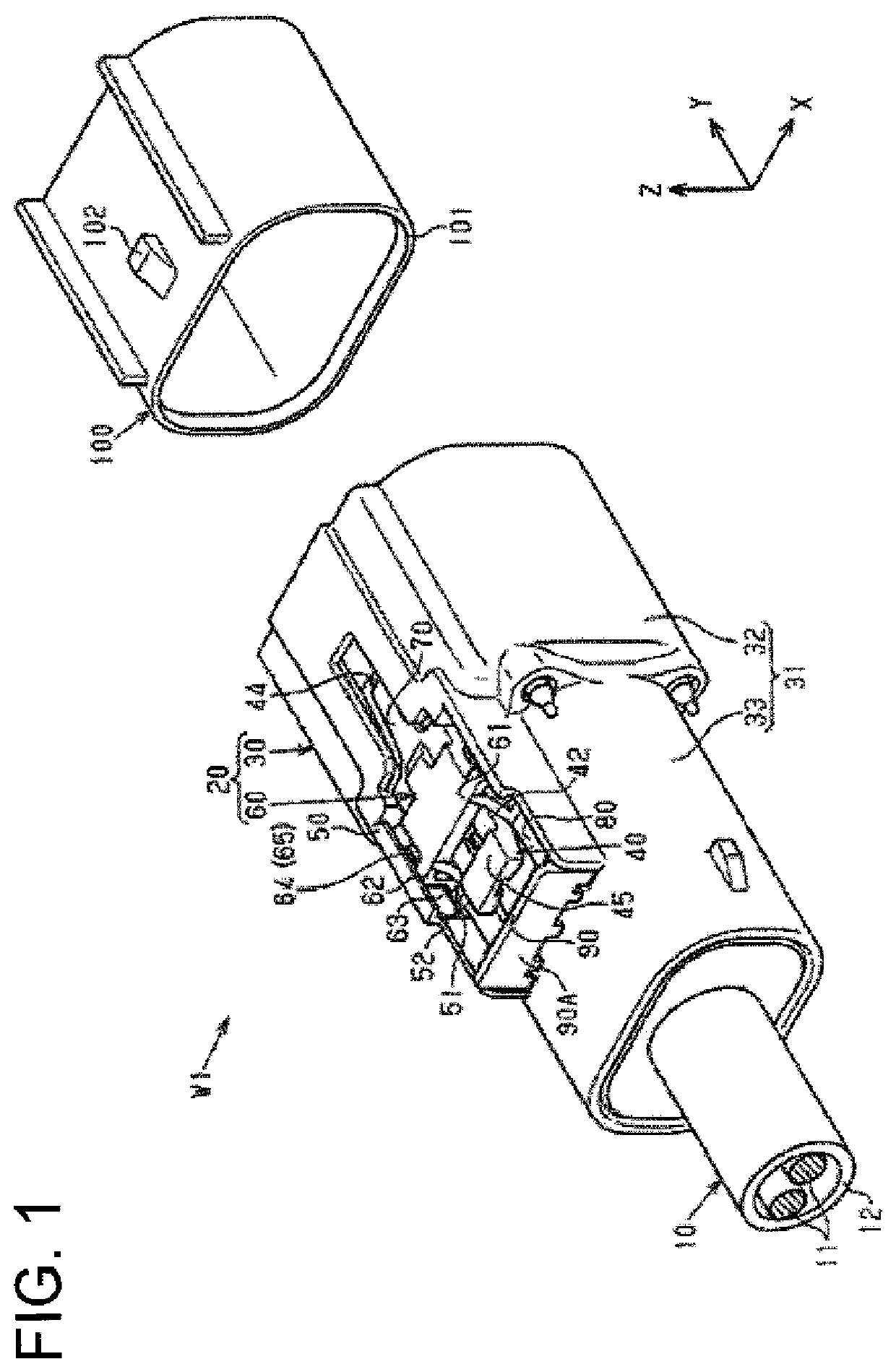
[0039]As shown in FIG. 1, a wiring harness W1 includes a wire 10 and a connector 20 mounted on an end part of...


PUM


Abstract

A connector position assurance member (60) includes a body (61), a resiliently displaceable lock (70) projecting forward from a front of the body (61) and a push-in suppressing member (80) projecting rearward from a rear of the body (61). The housing (30) includes a receptacle (31) and a lock arm (40) provided on an upper surface of the receptacle (31). The lock arm (40) includes a locking portion (44) to be locked to a projection (102) of a mating housing (100) and a connection releasing portion (45) for displacing the locking portion (44) by being pushed toward an outer peripheral surface of the receptacle (31). With the connector position assurance member (60) at a connection assurance position (CAP), the lock (70) is locked to the locking portion (44) and the push-in suppressing member (80) is between the upper surface of the receptacle (31) and the connection releasing portion (45).

Description

BACKGROUNDField of the Invention[0001]This disclosure relates to a connector, a connector position assurance member and a wiring harness.Related Art[0002]A connector composed of a male connector, a female connector to be connected to the male connector and a connector position assurance (CPA) member slidably mounted outside the female connector is known as an example of a conventional connector (see, for example, Japanese Unexamined Patent Publication No. 2012-064461). The CPA member includes a cantilevered CPA lock.[0003]In the connector of this type, if the male and female connectors are connected, a female-side lock of the female connector rides over a male-side lock of the male connector for locking. If the CPA member is slid in a connecting direction in this state, the CPA lock rides over the female-side lock and the male-side lock. In this way, the connection of the male connector and the female connector is assured.[0004]The above-described connector is provided with a connec...

Claims


Application Information

Patent Timeline
IPC IPC(8): H01R13/639H01R13/627
CPCH01R13/6272H01R13/639H01R13/6275H01R13/641
Inventor KURITA, ATSUSHI
Owner SUMITOMO WIRING SYST LTD
Why Eureka
Try Eureka