Method for driving optical pickup apparatus

Inactive Publication Date: 2012-08-09
FUNAI ELECTRIC CO LTD
View PDF11 Cites 1 Cited by
  • Summary
  • Abstract
  • Description
  • Claims
  • Application Information

AI Technical Summary

Benefits of technology

[0027]Moreover, it is preferred that the first stopping member includes a leaf spring, and the second stopping member includes a coil spring. With this constitution, because the first stopping member near the drive motor includes a leaf spring, contact between the nut and the drive motor can be reliably suppressed. Furthermore, because the second stopping member includes a coil spring, a constitution is created which is such that the movable lens is moved while being held between the nut and the coil spring at the time of the movement in the direction of the optical axis, which makes smooth and accurate lens movement possible without wobbling or the like.

Problems solved by technology

However, if the screw shaft is halted via a stopping member or urging member while it is rotating, there is a risk of wearing the surfaces that contact rotating portions such as the threaded portions or shaft portions at the time of gear tooth-skipping or disengaged rotating (hereinafter referred to collectively as “gear tooth-skippin

Method used


Image

  • Method for driving optical pickup apparatus
  • Method for driving optical pickup apparatus
  • Method for driving optical pickup apparatus

Examples


Example

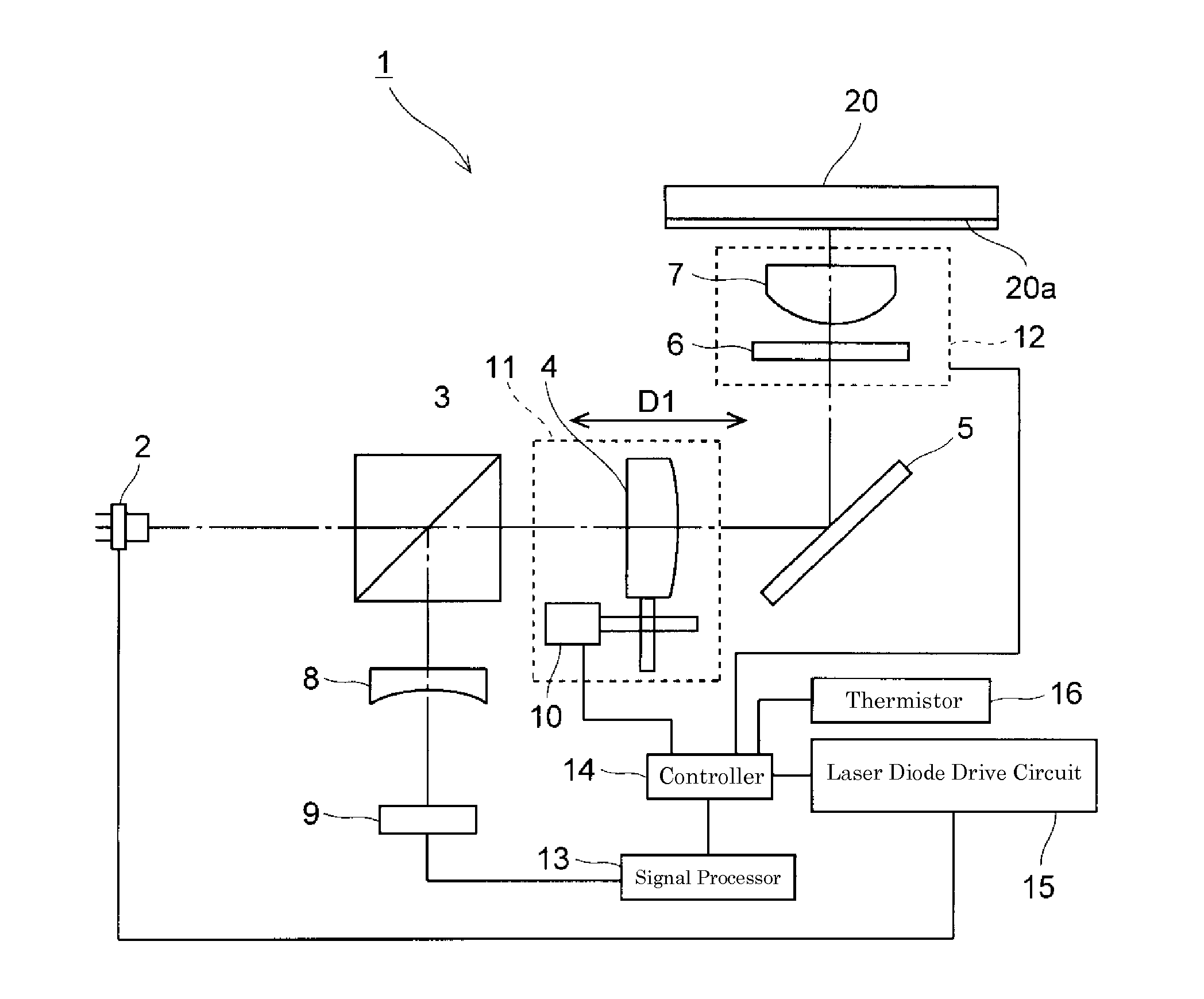
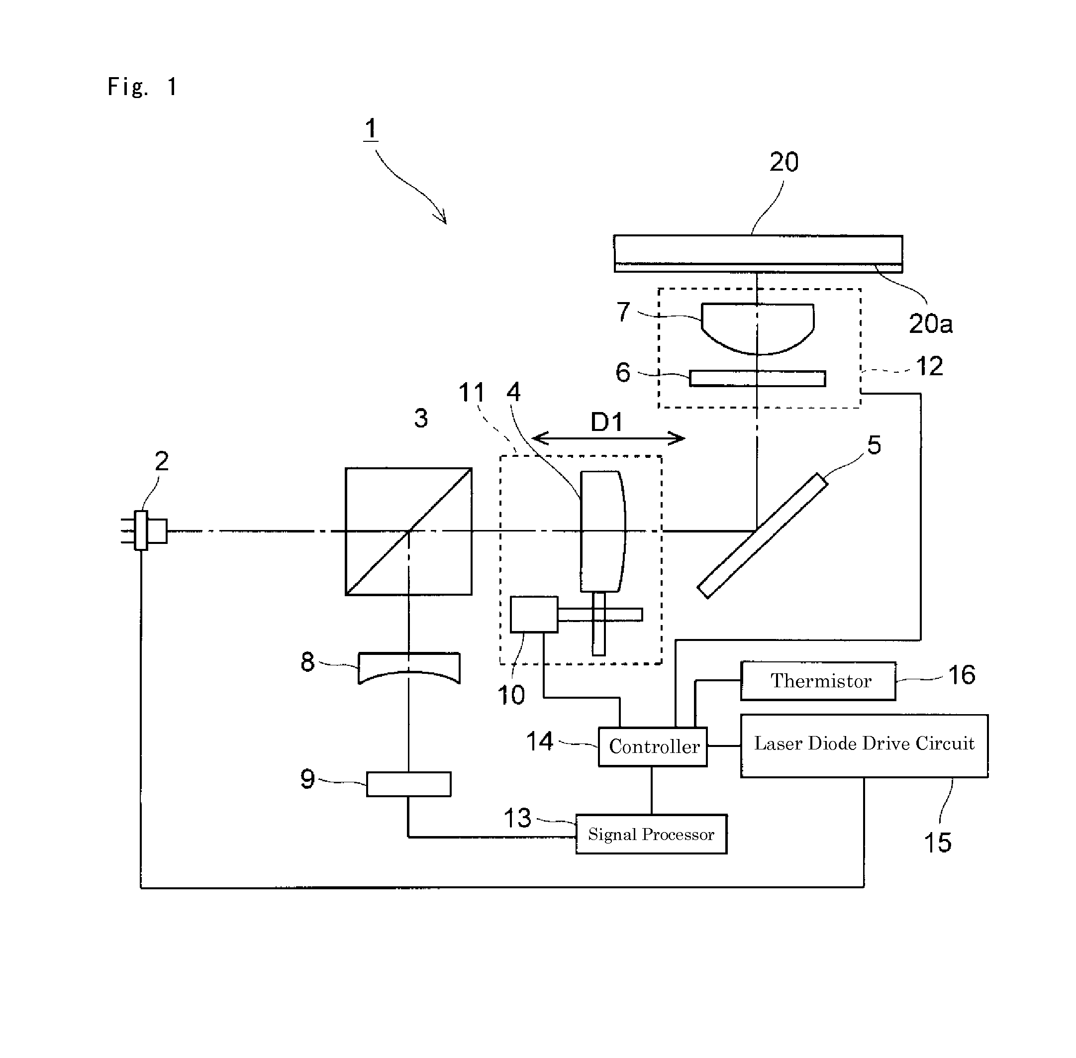
[0036]Preferred embodiments of the present invention will be described with reference to drawings. Note that the same symbols are used for the same constituent members, and detailed explanations are omitted as appropriate. First, one example of an optical pickup apparatus will be described with reference to FIG. 1.

[0037]The optical pickup apparatus 1 according to the present preferred embodiment is an apparatus that irradiates an optical disc 20 with laser light to record or playback data. The optical pickup apparatus 1 according to the present preferred embodiment preferably includes, for example, a laser diode 2 constituting the light source, a polarizing beam splitter 3, a collimating lens 4, a stand-up mirror 5, a quarter-wave plate 6, an objective lens 7, a cylindrical lens 8, and an optical detector 9 as shown in FIG. 1, and laser light is focused on a recording layer 20a of the optical disc 20 using the objective lens 7.

[0038]The laser diode 2 preferably is a semiconductor la...


PUM


Abstract

A method for driving an optical pickup apparatus which improves the durability of components that drive a movable lens that moves back and forth between an original position and a drive-limit position and achieves stable operability and an extended lifetime of the optical pickup apparatus performs a first step-drive in which a movable lens moves to an original-restoration start position by being driven a specified distance toward a drive-limit position, a second step-drive in which the movable lens thereafter moves to an original position by being driven toward the original position a distance equivalent to the distance from the drive-limit position to the original position, and a third step-drive in which the movable lens thereafter moves to a default position by being driven a specified distance.

Description

BACKGROUND OF THE INVENTION[0001]1. Field of the Invention[0002]The present invention relates to a method for driving an optical pickup apparatus that irradiates an optical disc with laser light to record or playback data.[0003]2. Description of the Related Art[0004]As disc-shaped recording media, many types of optical disc such as a compact disc (CD), a digital versatile disc (DVD), a high-density DVD (HD-DVD) and a Blu-ray Disc have been put into practical use in the past. With these types of optical discs, the wavelength of laser light used, the depth of the transparent layers extending down to the recording layer, and the like differ, so a single or a plurality of objective lenses are used to handle a plurality of types of optical disc.[0005]Furthermore, an optical pickup apparatus is used which irradiates an optical disc with laser light to record or playback data. The optical pickup apparatus is equipped with an objective lens that focuses laser light at a spot on the signal r...

Claims


Application Information

Patent Timeline
IPC IPC(8): G11B21/12G11B7/1376G11B7/1374
CPCG11B7/13925G11B7/1378
Inventor OKAMOTO, TAKAYUKI
Owner FUNAI ELECTRIC CO LTD
Why Eureka
Try Eureka