Immersion exposure apparatus and device manufacturing method

Inactive Publication Date: 2009-04-09
CANON KK
View PDF8 Cites 4 Cited by
  • Summary
  • Abstract
  • Description
  • Claims
  • Application Information

AI Technical Summary

Benefits of technology

[0011]The present invention has been made on the basis of the recognition of the above-described problems, and has as its object to suppress liquid leakag

Problems solved by technology

Still worse, when the liquid which fills the working distance leaks out due to some cause, this may exert an adverse influence on, e.g., electronic devices or mechanisms in the exposure apparatus.
When the liquid leaks out or the projection optical system and the substrate stage come into mechanical contact with each other, huge amounts of time are required for maintenance until recovery, resulting in deterioration in productivity.
Especially, assume that electric power supply to the substrate stage mechanism i

Method used


Image

  • Immersion exposure apparatus and device manufacturing method
  • Immersion exposure apparatus and device manufacturing method
  • Immersion exposure apparatus and device manufacturing method

Examples


Example

[0019]A preferred embodiment of the present invention will be described below with reference to the accompanying drawings.

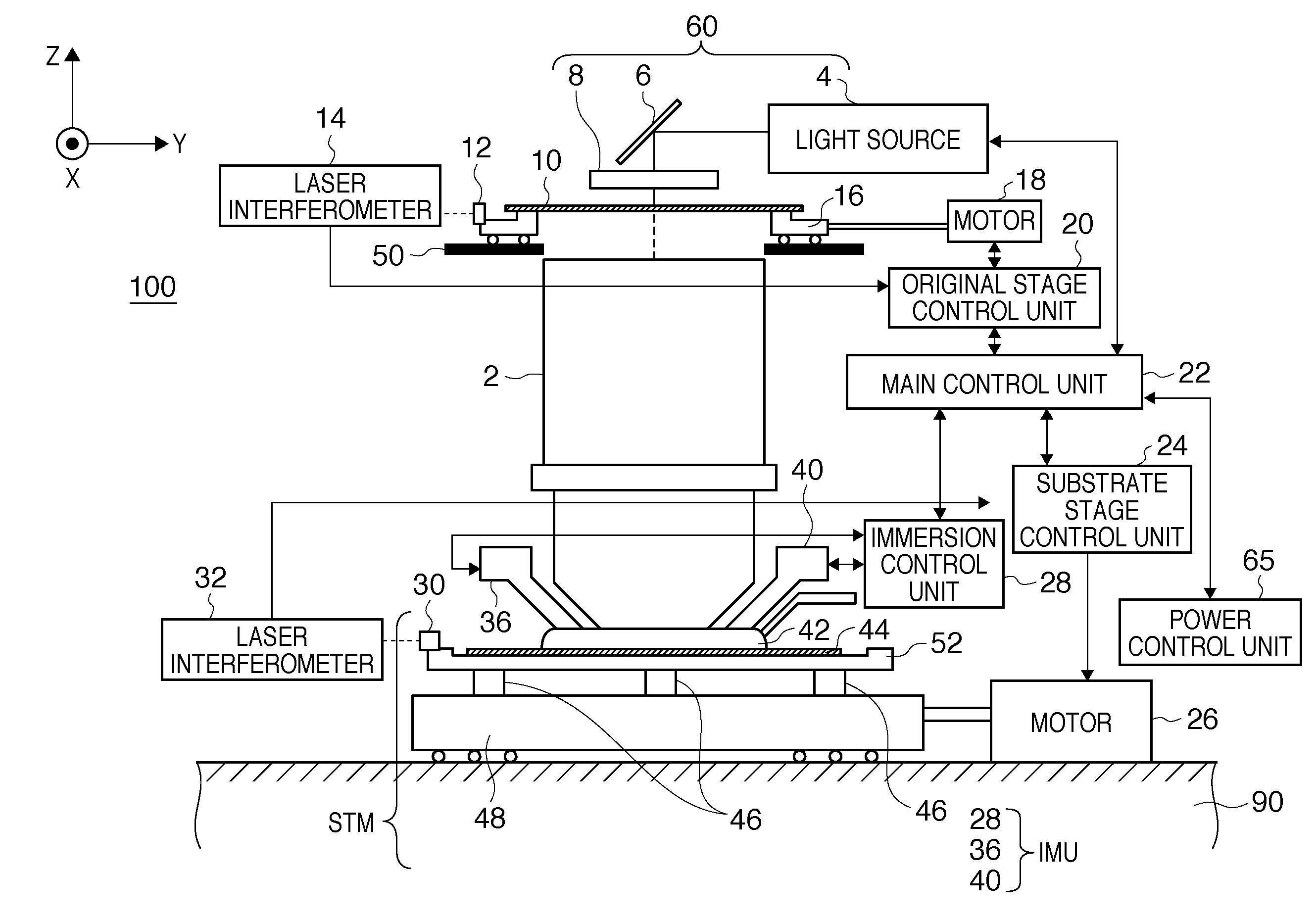
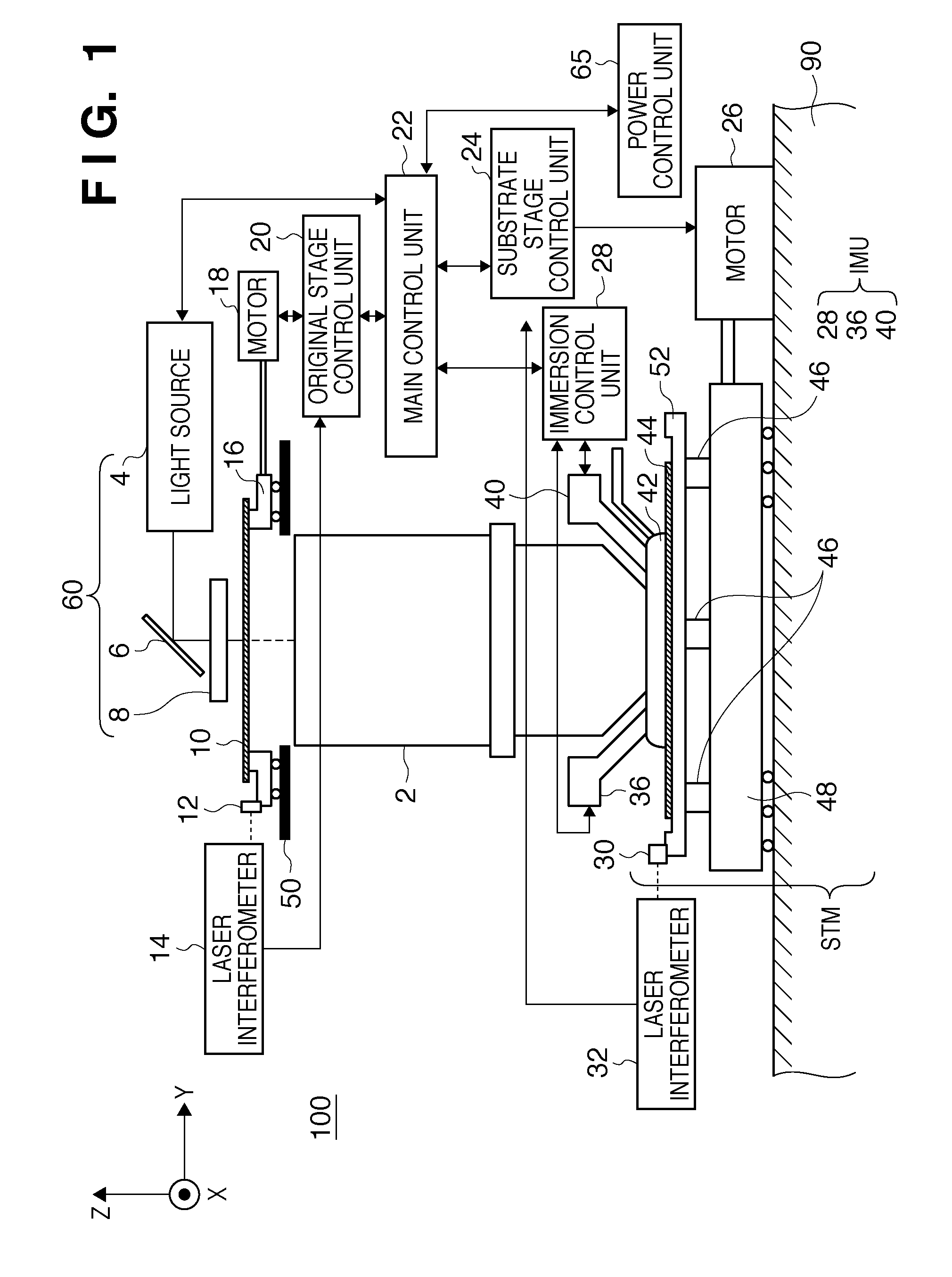
[0020]FIG. 1 is a block diagram schematically showing the arrangement of an immersion exposure apparatus according to a preferred embodiment of the present invention. Although an example in which the immersion exposure apparatus according to the present invention is applied to a scanner will be explained herein, the present invention is also applicable to a stepper.

[0021]An immersion exposure apparatus 100 according to a preferred embodiment of the present invention projects the pattern of an original (also called a reticle or mask) 10 onto a substrate (wafer) 44 via a projection optical system 2 and a liquid 42, thereby exposing the substrate 44. The substrate 44 is coated with a photosensitive agent. A latent image pattern is formed on the photosensitive agent by exposure. The projection optical system 2 has, e.g., a circular image field of view formed of the t...


PUM


Abstract

An immersion exposure apparatus which projects a pattern of an original onto a substrate to expose the substrate, comprises a substrate stage mechanism including a substrate stage configured to hold the substrate, an immersion unit configured to supply the liquid into a space between the substrate or the substrate stage and the projection optical system, and recover the liquid from above the substrate or the substrate stage, and a control unit configured to control the immersion unit to recover the liquid from above the substrate or the substrate stage, and then control the substrate stage mechanism to move the substrate stage to a retreat position, in response to a shutoff request for requesting shutoff of electric power supply to the substrate stage mechanism.

Description

BACKGROUND OF THE INVENTION[0001]1. Field of the Invention[0002]The present invention relates to an immersion exposure apparatus, which projects the pattern of an original onto a substrate via a projection optical system and a liquid, thereby exposing the substrate, and a device manufacturing method of manufacturing a device using the immersion exposure apparatus.[0003]2. Description of the Related Art[0004]Along with the advance of the micropatterning of semiconductor devices, the exposure light sources are shifting from high-pressure mercury lamps (the g-line and i-line) to the ones which emit light beams having shorter wavelengths, such as a KrF excimer laser and ArF excimer laser. To obtain a higher resolving power, it is necessary to increase the NA (numerical aperture) of the projection optical system, so the depth of focus is further decreasing. The relationship among these factors can be generally expressed by:(resolving power)=k1(λ / NA)(depth of focus)=±k2(λ / NA2)where λ is t...

Claims


Application Information

Patent Timeline
IPC IPC(8): G03B27/42G03B27/52
CPCG03F7/70341G03F7/70858G03F7/70725G03F7/70525G03F7/70533
Inventor OGINO, KAORU
Owner CANON KK
Why Eureka
Try Eureka