Path-Modifying Control System Managing Robot Singularities

a control system and robot technology, applied in the field of robot mechanisms, can solve the problems of reducing the reducing the degree of freedom of the robot, and inverse kinematics problems,

Active Publication Date: 2021-01-07
WISCONSIN ALUMNI RES FOUND
View PDF9 Cites 12 Cited by
  • Summary
  • Abstract
  • Description
  • Claims
  • Application Information

AI Technical Summary

Benefits of technology

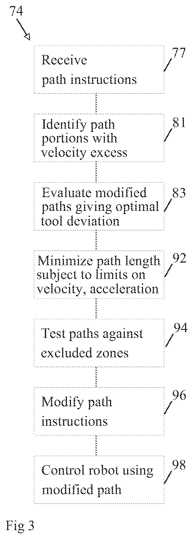
[0010]The present invention provides a robot-mechanism controller that identifies portions of a path that will produce excessive joint motion because of the singularity and produces a modified path according to a minimization of change in orienta

Problems solved by technology

Calculation of the joint positions when the only the desired path of the tool is known and the relative joint positions are unknown (the “inverse kinematic” problem) is much more difficult than the forward kinematic problem, often providing multiple solutions and requiring iterative techniques.
Finding practical solutions to the inverse kinematics problem is complicated by the presence of robot “singularities” which can occur, in one example, when two different axes of the robot align.
This alignment effectively reduces one degree of freedom of the robot and can cause extremely high rates of joint movement in the other axes as those axes absorb the burden of movement.
Whe

Method used


Image

  • Path-Modifying Control System Managing Robot Singularities
  • Path-Modifying Control System Managing Robot Singularities
  • Path-Modifying Control System Managing Robot Singularities

Examples


embodiment 1

[0198]This single virtual-displacement procedure is applied in the Preferred Embodiment 1) over the course of the singularity locating maneuver to maintain the minimum tool deviation θ7, 2) when solving for the point giving the least-maximum deviation on the adjusted path of a spherical wrist, and 3) in order to pass through the least-maximum point upon executing the singularity avoidance maneuver

[0199]With an offset wrist, finding the least-maximum point on the adjusted path requires guiding joints 4, 5 and 6 with joints 1, 2, 3, 7, 8 and 9 passive to meet rate CV7(t)=0 for each of the constant active-joint rates CV4=1, CV5=1 and CV6p=1. Applying Eq. (A12) to these three virtual displacements having rate vectors CV,r for 1≤r≤3 gives the linear system of equations

[CγV7,1,1CγV7,2,1CγV7,3,1CγV7,1,2CγV7,2CγV7,3,2CγV7,1,3CγV7,2,3CγV7,3,3][γ1[k]γ2[k]γ3[k]]+(k+1)[B1B2B3]=0Br=CβV7,r[k+1]-CV7,r[k+1],1≤r≤3(A14)

[0200]For example, constant coefficient CγV7,3,1 at the end of the first row in E...

case b

[0226]In case b), both the quadratic and the bounding polynomial f̆p(x) are initially of upward slope and downward curvature. Both functions will continue to increase until they reach their respective slope inflection points. Hence f̆p(x) has no real root until after its inflection Between its inflection point and the positive-real root of the downwardly curved quadratic, f̆p(x) has one real root.

[0227]In case e) where both functions are initially of positive slope and upward curvature, the bounding polynomial f̆p(x) will continue to increase until it passes first its curvature inflection followed by its slope inflection. After that, f̆p(x) is monotone down if f̆3,p(x) has at least one non-zero coefficient. It follows that f̆p(x) has only one real root on the positive real line. As the quadratic has no real root on that interval, f̆p(x) would need to be sampled at increasing intervals to determine where it changes sign, marking the upper limit on a single real root. This condition ...


PUM


Abstract

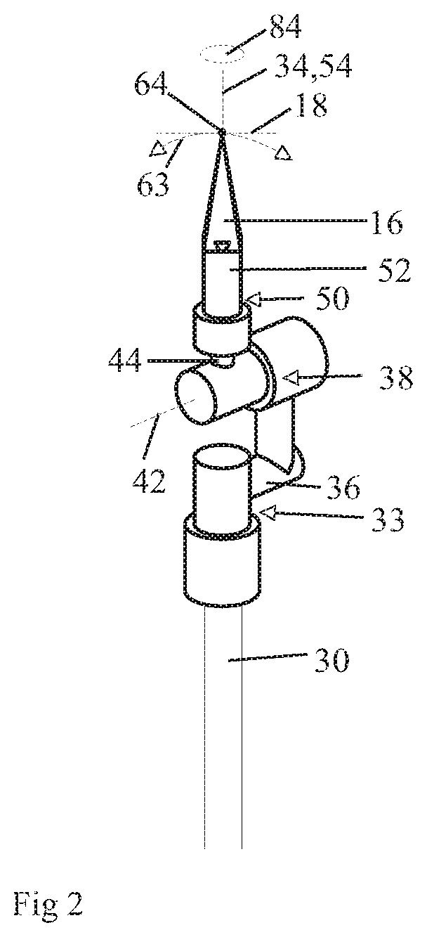
A controller for robot arms and the like having mechanical singularities identities paths near the singularities and modifies those paths to avoid excessive joint movement according to a minimization of tool orientation deviation to produce alternative paths that minimize changes in the tool orientation such as can affect application such as welding, sealant application, coating and the like.

Description

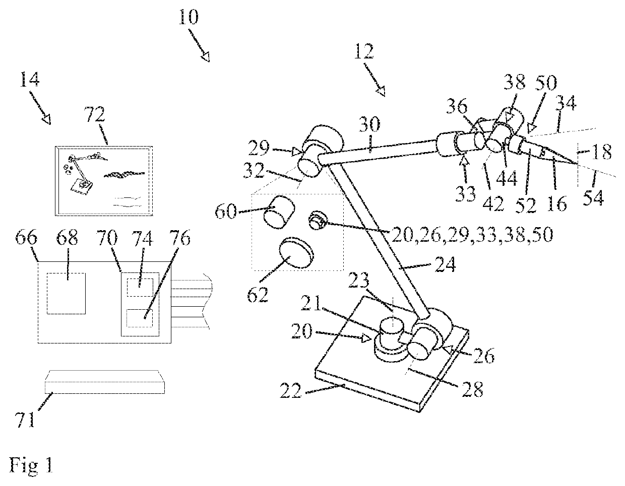
CROSS REFERENCE TO RELATED APPLICATION[0001]This application claims the benefit of U.S. provisional application 62 / 869,244 filed Jul. 1, 2019 of which is hereby incorporated by reference.BACKGROUND OF THE INVENTION[0002]The present invention relates generally to robotic mechanisms providing for multiple axes of movement defined by links joined by motor driven joints, and in particular to a control system for such robotic mechanisms that can accommodate problems presented by mechanism singularities.[0003]Robotic mechanisms (robots) have wide use in manufacturing applications where a tool held by a robotic arm is moved along a path at a controlled rate. Such applications include, for example, welding applications where a welding bead must be applied to join materials, or coating application such as painting or the dispensing of sealants. In such applications, a path describing the motion of a tool and its orientation is prepared by a programmer or programming tool. This path must then...

Claims


Application Information

Patent Timeline
IPC IPC(8): B25J9/16B25J13/08
CPCB25J9/1666B25J13/088B25J11/0075B25J9/1605B25J9/163B25J9/1651G05B2219/40367G05B2219/40333B25J9/1643B25J9/046B25J11/005
Inventor MILENKOVIC, PAUL H.
Owner WISCONSIN ALUMNI RES FOUND
Why Eureka
Try Eureka