
Traffic monitoring apparatus, traffic monitoring system, traffic monitoring method, and non-transitory computer readable medium storing program

Pending Publication Date: 2021-01-14
NEC CORP
View PDF0 Cites 2 Cited by
  • Summary
  • Abstract
  • Description
  • Claims
  • Application Information

AI Technical Summary

Benefits of technology

The present disclosure provides a device and method for monitoring traffic to determine the cause of congestion. This can help improve the efficiency of traffic management and prevent long delays for drivers.

Problems solved by technology

However, traffic infrastructure such as roads, railroads, buses and the like has not been sufficiently developed, which causes serious traffic congestion due to a rapid increase in a traffic amount.

Method used


Image

  • Traffic monitoring apparatus, traffic monitoring system, traffic monitoring method, and non-transitory computer readable medium storing program
  • Traffic monitoring apparatus, traffic monitoring system, traffic monitoring method, and non-transitory computer readable medium storing program
  • Traffic monitoring apparatus, traffic monitoring system, traffic monitoring method, and non-transitory computer readable medium storing program

Examples


example embodiment

Outline of Example Embodiment According to Present Disclosure

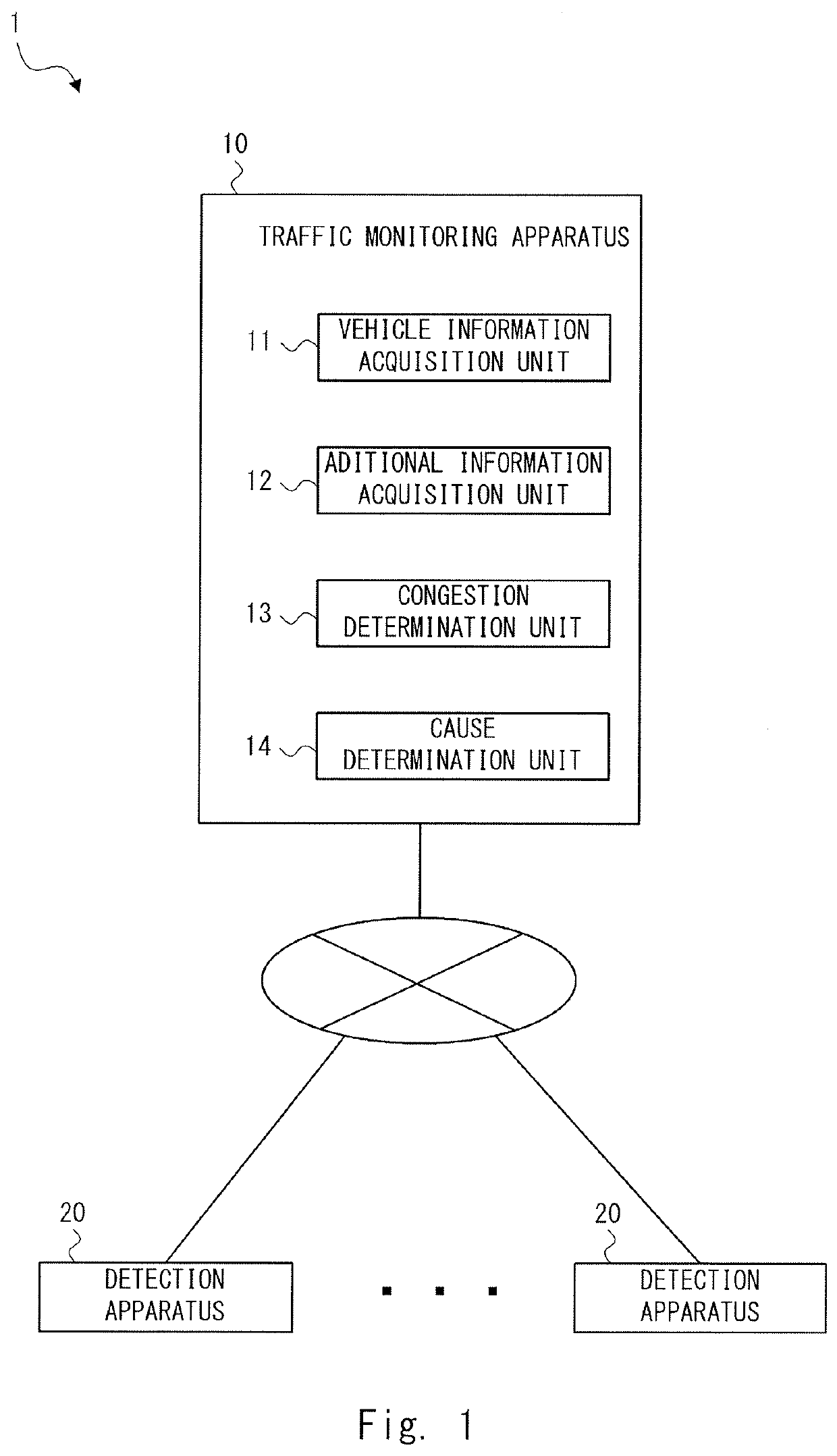
[0033]Prior to giving a description of an example embodiment of the present disclosure, an outline of the example embodiment according to the present disclosure will be described. FIG. 1 is a diagram showing the outline of a traffic monitoring system 1 according to the example embodiment of the present disclosure. The traffic monitoring system 1 includes a traffic monitoring apparatus 10 and at least one detection apparatus 20. The detection apparatus 20 and the traffic monitoring apparatus 10 are connected to each other in such a way that they can communicate with each other via a wired or wireless network.

[0034]The detection apparatus 20 is, for example, a camera, a sensor or the like. The detection apparatus 20 detects a state of a road and transmits data indicating the results of the detection to the traffic monitoring apparatus 10. In particular, the detection apparatus 20 detects a state of an area in the vicinity of...

first example embodiment

[0037]Hereinafter, with reference to the drawings, example embodiments will be described. For the sake of clarification of the description, the following description and the drawings are omitted and simplified as appropriate. Throughout the drawings, the same elements are denoted by the same reference symbols and overlapping descriptions are omitted as appropriate.

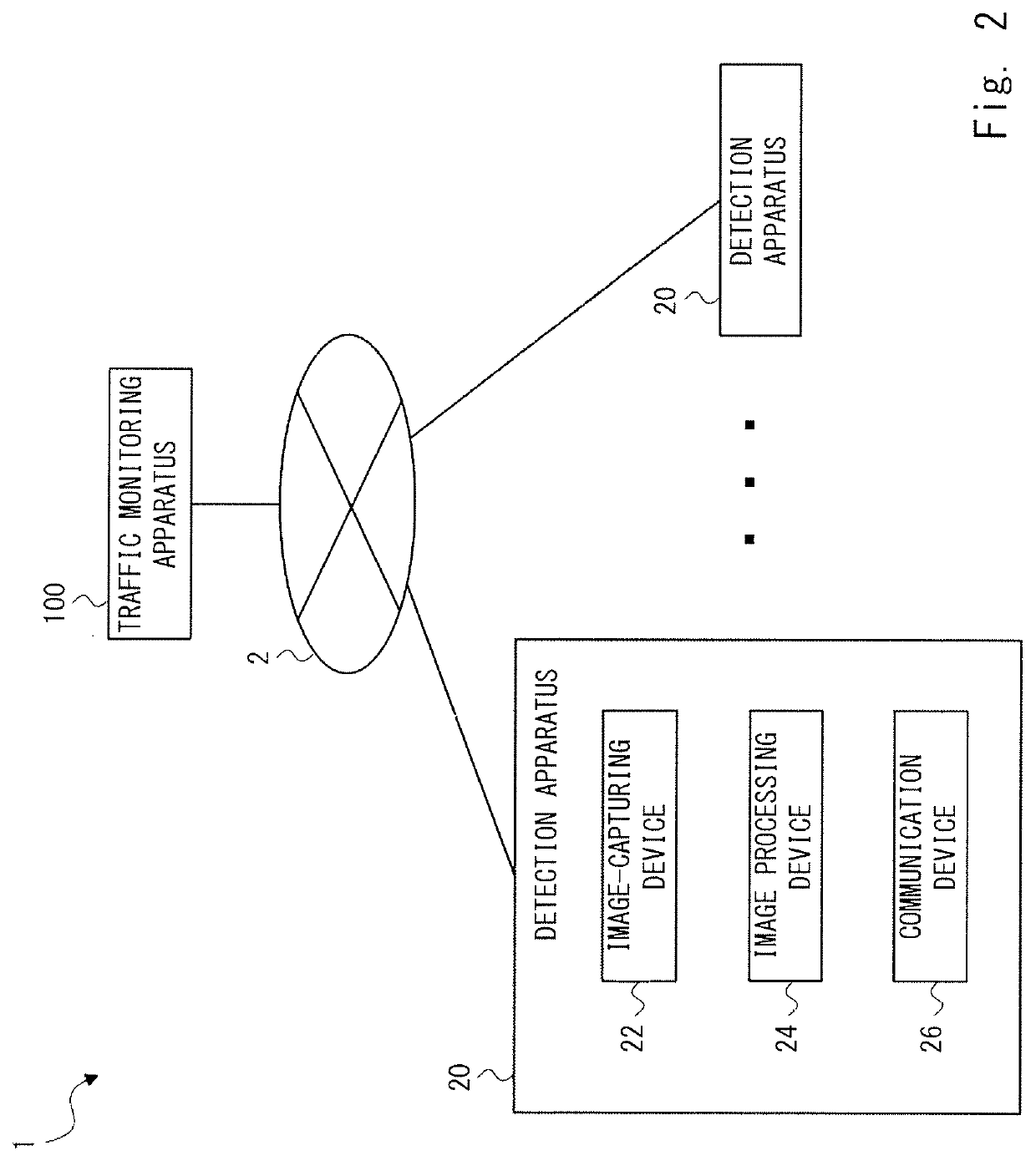
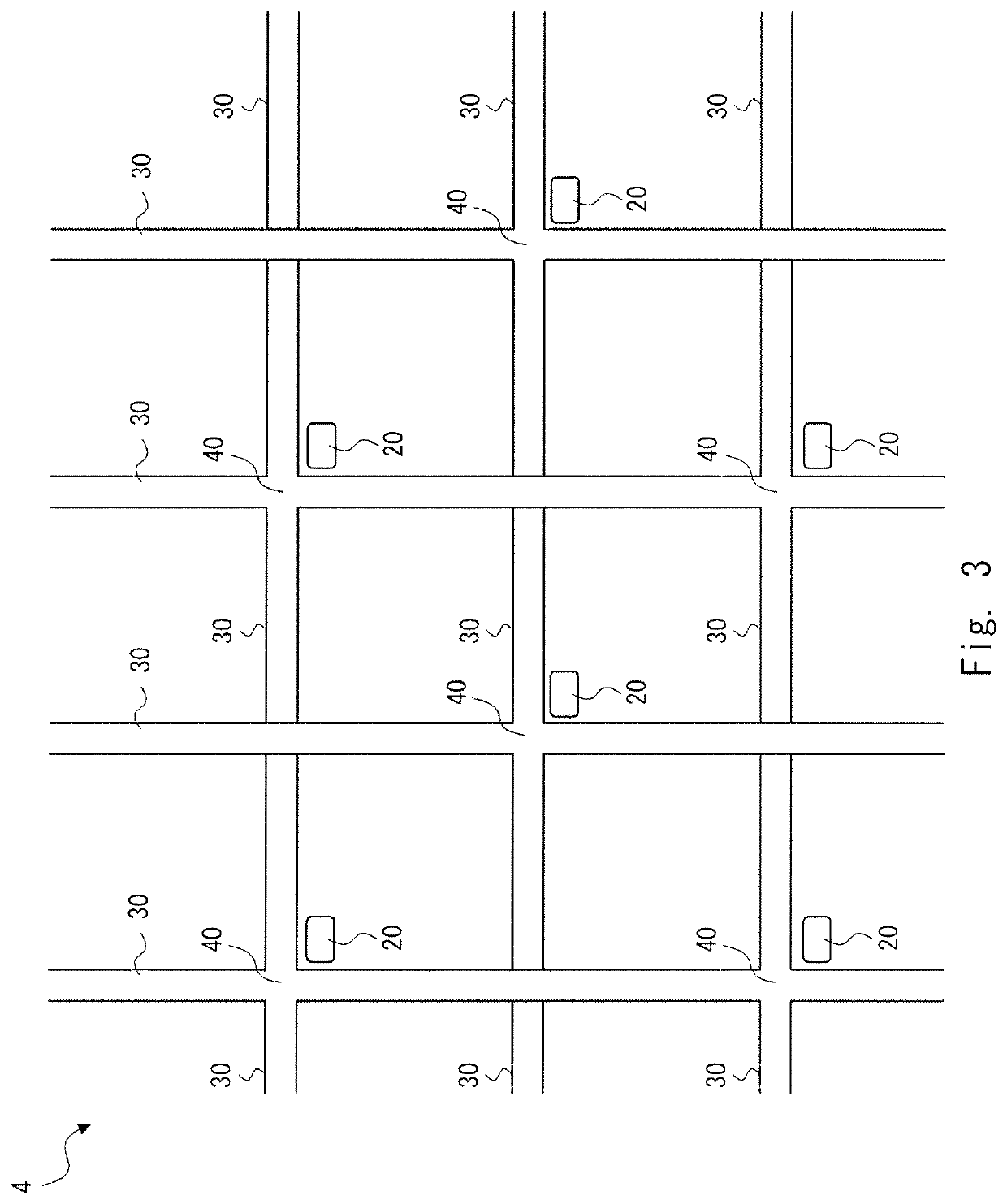
[0038]FIG. 2 is a diagram showing a traffic monitoring system 1 according to a first example embodiment. The traffic monitoring system 1 is formed of a plurality of detection apparatuses 20 and a traffic monitoring apparatus 100. The traffic monitoring apparatus 100 corresponds to the traffic monitoring apparatus 10 shown in FIG. 1. Each of the plurality of detection apparatuses 20 and the traffic monitoring apparatus 100 are connected to each other in such a way that they can communicate with each other via a wired or wireless network 2. The detection apparatus 20 may be installed in the vicinity of an intersection.

[0039]...

modified examples

[0095]Note that the present disclosure is not limited to the aforementioned example embodiments and may be changed as appropriate without departing from the spirit of the present disclosure. For example, in the aforementioned flowcharts, the order of each process (step) may be changed as appropriate. Further, one or more of the plurality of processes (steps) may be omitted. For example, the process of S160 in FIG. 6 may be omitted. Further, one or more of the processes of S114, S118, and S122 in FIG. 7 may be omitted.

[0096]Further, while the cause information storage unit 122 and the countermeasure information storage unit 132 are provided in the traffic monitoring apparatus 100 in the aforementioned example embodiments, the configuration thereof is not limited thereto. The cause information storage unit 122 and the countermeasure information storage unit 132 may not be provided in the traffic monitoring apparatus 100. The cause information storage unit 122 and the countermeasure in...


PUM


Abstract

A traffic monitoring apparatus capable of determining a cause of traffic congestion more definitely is provided. A traffic monitoring apparatus (10) includes a vehicle information acquisition unit (11), an additional information acquisition unit (12), a congestion determination unit (13), and a cause determination unit (14). The vehicle information acquisition unit (11) acquires vehicle information regarding a travelling state of a vehicle from data received from a detection apparatus (20). The additional information acquisition unit (12) acquires additional information regarding objects that are other than the travelling vehicle and are present in the vicinity of the travelling vehicle. The congestion determination unit (13) determines, for each of a plurality of lanes on the road, whether or not congestion is occurring based on the vehicle information. The cause determination unit (14) determines, for the lane that has been determined to be congested, a cause of congestion using at least the additional information.

Description

TECHNICAL FIELD[0001]The present disclosure relates to a traffic monitoring apparatus, a traffic monitoring system, a traffic monitoring method, and a non-transitory computer readable medium storing a program.BACKGROUND ART[0002]In emerging countries etc., concentration of the population in urban areas has been rapidly occurring along with economic growth. However, traffic infrastructure such as roads, railroads, buses and the like has not been sufficiently developed, which causes serious traffic congestion due to a rapid increase in a traffic amount. In order to deal with the above situation, there is a technique of managing actual traffic situations in a road network by a traffic control apparatus installed in a traffic control center and implementing traffic measures such as controlling signal lights installed in an intersection and sending a notification of traffic situations indicating congestion, traffic regulations or the like to drivers.[0003]With regard to the above techniq...

Claims


Application Information

Patent Timeline
IPC IPC(8): G08G1/01G08G1/04G08G1/056G06K9/00
CPCG08G1/0145G08G1/0133G06K9/00785G08G1/056G08G1/04G08G1/0116G06V20/53G06V20/54
Inventor YUSA, MICHIHIKO
Owner NEC CORP
Learn More