Ceiling fan and assembling method thereof

a ceiling fan and a technology of a ceiling fan body are applied in the field of ceiling fans, which can solve the problems of inconvenient use, difficult to provide stagnant airflow in the vertically downward region of the ceiling fan, etc., and achieve the effect of improving the comfort of the user, air volume and flow ra

Active Publication Date: 2021-02-11
LG ELECTRONICS INC
View PDF0 Cites 1 Cited by
  • Summary
  • Abstract
  • Description
  • Claims
  • Application Information

AI Technical Summary

Benefits of technology

[0111]According to the present disclosure, the air volume and the flow rate may be more improved due to the dual blades as compared to the conventional ceiling fan. Accordingly, the sense of comfort of the user may be improved.
[0112]In addition, the improved air volume and flow rate are provided, thereby rapidly lowering the indoor temperature even in hot weather, and rapidly raising the indoor temperature in cold weather. In other words, the discomfort of the user may be rapidly resolved.
[0113]In addition, the circulation of air in the room may be rapidly improved.
[0114]In addition, since the air-flow reach range is increased, it is possible to minimize or prevent the stagnation of the air flow in a local space of the room.
[0115]In addition, the red zone of the air flow formed under the ceiling fan along the central axis of the ceiling fan is minimized, thereby providing the uniform and constant sense of comfort to the user.
[0116]Further, the uniform air flow rate and temperature distribution may be formed in the whole indoor space. Accordingly, the sense of comfort may be provided to the user to the same extent regardless of the positions of the user.

Problems solved by technology

First, there is a problem that the airflow is stagnated in the vertically downward region of the ceiling fan, that is, the region where the rotation center of the plurality of blades is located.
Second, as the smaller air flow volume and a slower flow rate are provided, there is a problem that the air-flow reach range is narrow and the temperature sensed by the user varies depending on the indoor position of the user. Accordingly, there is a problem that it is difficult to provide the sense of comfort to the user because the air flow is stagnated in the local space where the airflow fails to reach.
Third, since greater vibration and noise are generated, there is a problem of causing the inconveniences in a user's life such as sleeping.
Fourth, there is a problem of increasing coupling points for the coupling between blades to form a space at the inner center of a plurality of blades. Accordingly, the vibration, the noise, or the decoupling may be generated due to the rotation of the blade. Accordingly, the rotation stability of the ceiling fan may be deteriorated.
Fifth, there is a problem that the coupling between the components is complicated and the separation is relatively difficult. Therefore, there is a disadvantage that the installation convenience and manageability of the ceiling fan are inferior.

Method used


Image

  • Ceiling fan and assembling method thereof
  • Ceiling fan and assembling method thereof
  • Ceiling fan and assembling method thereof

Examples


Embodiment Construction

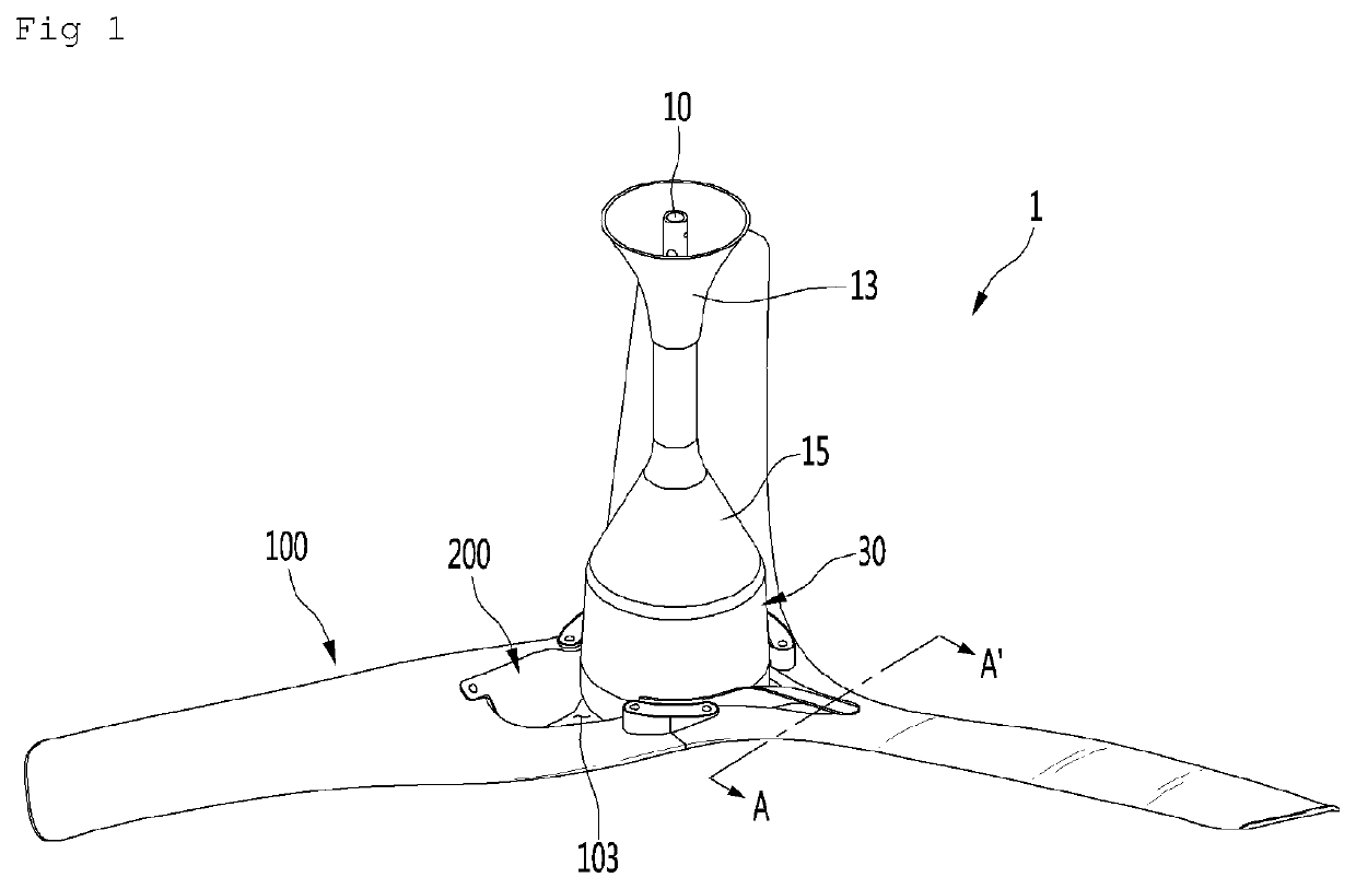
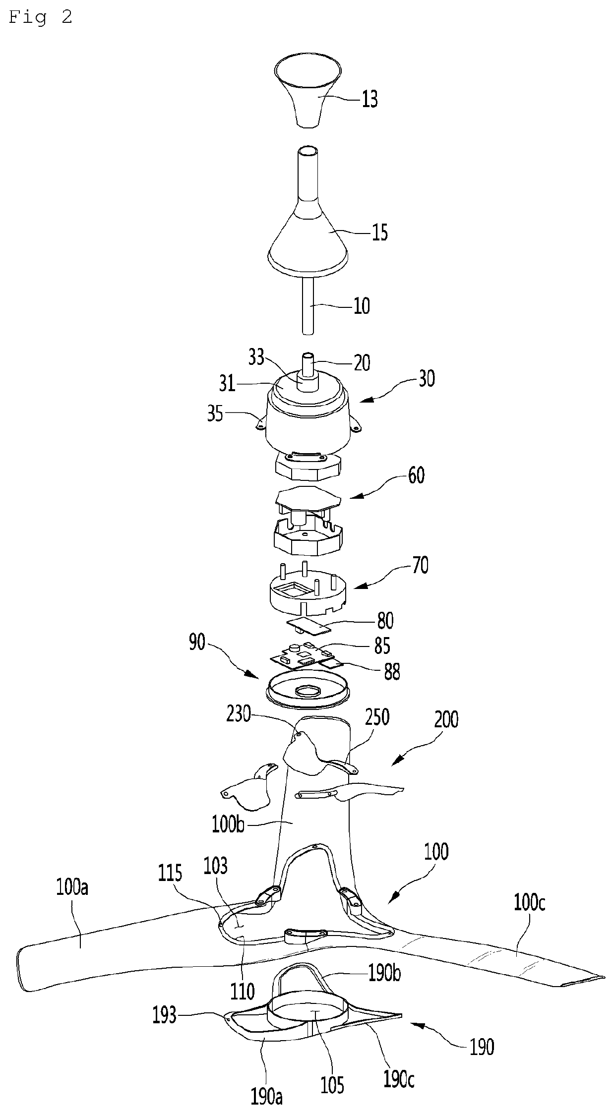
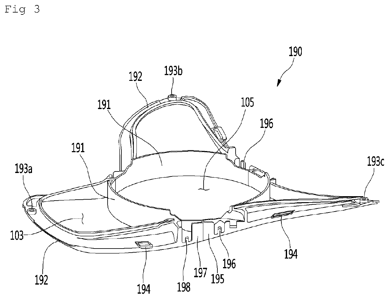
[0154]Hereinafter, some embodiments of the present disclosure will be described in detail with reference to accompanying drawings. In the following description, the same reference numerals will be assigned to the same components even though the components are illustrated in different drawings. In addition, in the following description of an embodiment of the present disclosure, a detailed description of well-known features or functions will be ruled out in order not to unnecessarily obscure the gist of the present disclosure.

[0155]In the following description of components according to an embodiment of the present disclosure, the terms ‘first’, ‘second’, ‘A’, ‘B’, ‘(a)’, and ‘(b)’ may be used. The terms are used only to distinguish relevant components from other components, and the nature, the order, or the sequence of the relevant components is not limited to the terms. When a certain component is “linked to”, “coupled to”, or “connected with” another component, the certain compone...


PUM


Abstract

According to an embodiment of the present disclosure, a ceiling fan may include a shaft coupled to a ceiling, a cover to surround the shaft, a main blade having a blade hole which is a space open inward, and a sub-blade positioned in the blade hole. The ceiling fan may resolve the red zone of the air flow and may improve air volume and the flow rate due to the dual blades.

Description

TECHNICAL FIELD[0001]The present disclosure relates to a ceiling fan and a method for assembling the same.BACKGROUND ART[0002]A flow generating device refers to a device which drives a fan to generate air flow and to provide the generated air flow to a user. Such a flow generating device is usually called a fan.[0003]The flow generating device may be variously classified according to a flow generation manner, a function, an installation manner, and the like. A device, which is installed on a wall surface or a ceiling, of the flow generating device to generate an air flow is called a ceiling fan.[0004]The ceiling fan has been widely used in homes or malls because the ceiling fan may provide economic advantages to the user as the ceiling fan requires power less than an air conditioner or a general fan.[0005]Generally, the ceiling fan includes a drive motor to provide power and a plurality of blades connected to a shaft of the drive motor.[0006]The ceiling fan may circulate air in a ro...

Claims


Application Information

Patent Timeline
Patent Type & Authority Applications(United States)
IPC IPC(8): F04D25/08F04D29/38
CPCF04D25/088F04D29/646F04D29/384F04D29/682F04D29/684F04D29/34F04D29/681F04D29/325F04D29/38F04D29/644
Inventor KIM, TAEJUNDHIMAN, ATULSINGH, SHIVENDRAPARK, JEEMANMUN, YEONGCHEOLPARK, WONSUKOH, SLYOUNGCHOI, SEOKHO
Owner LG ELECTRONICS INC
Why Eureka
Try Eureka