Backlight module and in vehicle display device

Active Publication Date: 2021-03-04
WUHAN CHINA STAR OPTOELECTRONICS TECH CO LTD
View PDF0 Cites 0 Cited by
  • Summary
  • Abstract
  • Description
  • Claims
  • Application Information

AI Technical Summary

Benefits of technology

[0039]In the present disclosure, the bracket layer is disposed between the diffusion plate and the light board of the backlight module. The bracket layer is configured to support the diffusion plate and space the light board apart from the diffusion plate to form the light mixture space. By adjusting a height o

Problems solved by technology

However, the sealant frame is made of a harder material, so it is not convenient to adjust a ratio of a distance between the backlight source and the diffusion plate to a thickness of the diffusion plate.
Therefore, it is easy to cause a problem of “starry” light and shadows, and hence the display quality of the display device is compromised.
Moreover, the sealant frame is produced at higher production costs, and its manufacturing process is complicated

Method used


Image

  • Backlight module and in vehicle display device
  • Backlight module and in vehicle display device
  • Backlight module and in vehicle display device

Examples


first embodiment

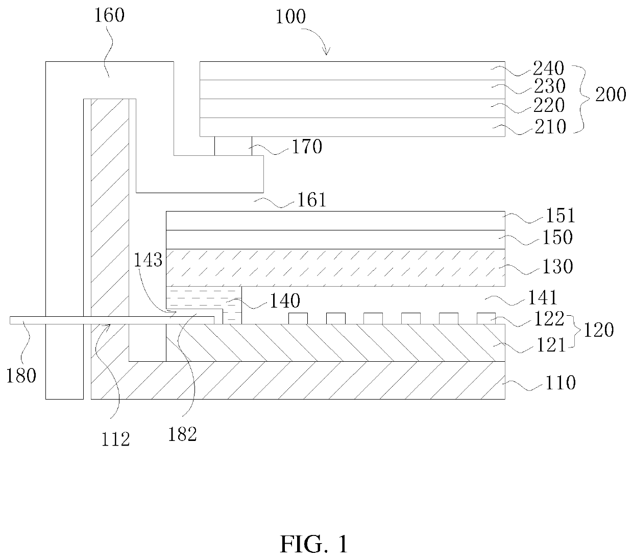
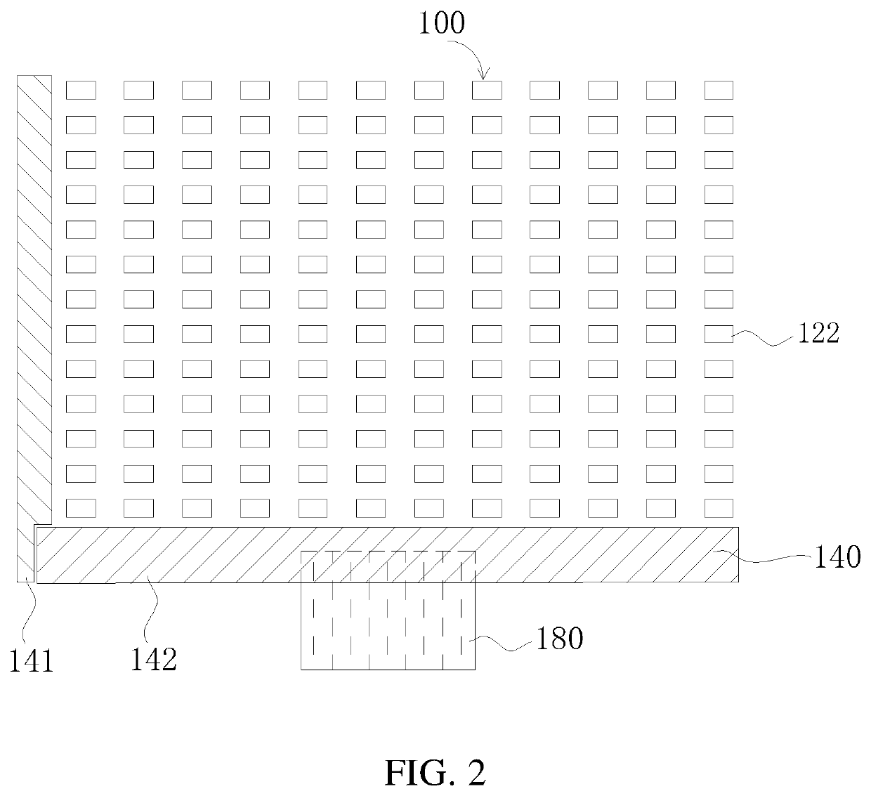
[0047]The present disclosure provides a backlight module which will be described in detail below in conjunction with FIGS. 1 to 2. FIG. 1 is a cross-sectional structural view illustrating a backlight module 100 according to one embodiment of the present disclosure. The backlight module 100 comprises a back plate 110, a light board 120, a diffusion plate 130, and a bracket layer 140. The light board 120 is attached to the back plate 110 by a thermal conductive adhesive tape. The diffusion plate 130 is disposed at one side of the light board 120 away from the back plate 110. The bracket layer 140 is disposed between the light board 120 and the diffusion plate 130, wherein the bracket layer 140 is configured to support the diffusion plate 130 and space the light board 120 apart from the diffusion plate 130 to form a light mixture space 141. A gap between adjacent two surfaces of the light board 120 and the diffusion plate 130 is the light mixture space 141. A light emitted from the lig...

second embodiment

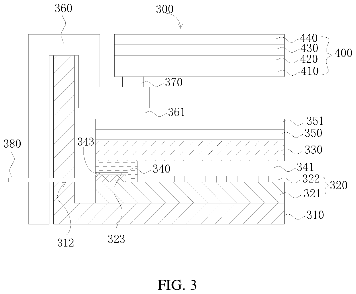
[0057]The present disclosure provides a backlight module which will be described in detail below in conjunction with FIGS. 3 and 4. Referring to FIG. 3, it is a cross-sectional structural view illustrating a backlight module 300 according to one embodiment of the present disclosure. The backlight module 300 comprises a back plate 310, a light board 320, a diffusion plate 330, and a bracket layer 340. The light board 320 is attached to the back plate 310 by a thermal conductive adhesive tape. The diffusion plate 330 is disposed at one side of the light board 320 away from the back plate 310. The bracket layer 340 is disposed between the light board 320 and the diffusion plate 330, wherein the bracket layer 340 is configured to support the diffusion plate 330 and space the light board 320 apart from the diffusion plate 330 to form a light mixture space 341. A gap between adjacent two surfaces of the light board 320 and the diffusion plate 330 is the light mixture space 341. A light em...


PUM


Abstract

The present disclosure provides a backlight module and an in-vehicle display device. The backlight module includes a back plate, a light board, a diffusion plate, and a bracket layer. The bracket layer is arranged between the light board and the diffusion plate. The bracket layer is used to support the diffusion plate and spaces the light board apart from the diffusion plate to form a light mixture space. By adjusting a height of the bracket layer, it is convenient to adjust a distance of the light mixture space formed between the diffusion plate and the light board. Accordingly, backlight display performance of the backlight module and the in-vehicle display device is improved.

Description

1. FIELD OF DISCLOSURE[0001]The present invention relates to a field of display technology and in particular, to a backlight module and an in-vehicle display device.2. DESCRIPTION OF RELATED ART[0002]With the development of vehicles and transportation, more and more information needs to be acquired during vehicle rides, and the driver's need for information interaction has also increased. As a kind of vehicle information carriers, an in-vehicle display can be used to display videos, images, and the like to intuitively and effectively disseminate information and realize many information interactions.[0003]At present, a backlight source of an in-vehicle liquid crystal display (LCD) device is spaced apart from a diffusion plate by a sealant frame to form a light mixture gap of a certain distance. However, the sealant frame is made of a harder material, so it is not convenient to adjust a ratio of a distance between the backlight source and the diffusion plate to a thickness of the diff...

Claims


Application Information

Patent Timeline
IPC IPC(8): G02F1/13357
CPCG02F1/133603G02F2001/133612G02F1/133608G02F1/133606G02F1/133609G02F1/133611G02F1/133612
Inventor JIN, FUBAO
Owner WUHAN CHINA STAR OPTOELECTRONICS TECH CO LTD
Why Eureka
Try Eureka