Light field based reflection removal

a light field and reflection technology, applied in the field of image processing, can solve the problem that traditional methods using unstructured collection of viewpoints are almost impossible to achiev

Pending Publication Date: 2021-03-18
SHANGHAI TECH UNIV
View PDF0 Cites 1 Cited by
  • Summary
  • Abstract
  • Description
  • Claims
  • Application Information

AI Technical Summary

Benefits of technology

[0009]Preferably, the transmitted layer is of low rank.

Problems solved by technology

Our method even works on dynamic scenes (i.e., video), which would be almost impossible for traditional methods using an unstructured collection of viewpoints.

Method used


Image

  • Light field based reflection removal
  • Light field based reflection removal
  • Light field based reflection removal

Examples


Embodiment Construction

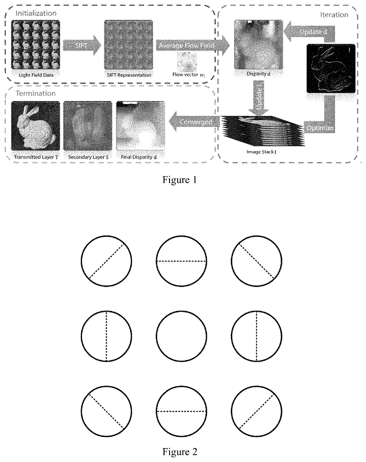
[0023]In accordance with embodiment of the present invention, a method of processing light field images for separating a transmitted layer from a reflection layer is provided.

[0024]In accordance with embodiments of the present invention, the light field of the scene (transmitted layer) with a secondary layer (e.g., reflection) is captured. The inputs are light field images from different viewpoints, and the central view is used as the reference view.

[0025]For each camera in the light field, polarizers are applied to the cameras with different polarization angles. Most of light in the real life is unpolarized, and upon being reflected by an interface, the light will have different polarization than that of the transmitted light. Different part of the reflection can be captured, which are useful to separate the transmitted layer.

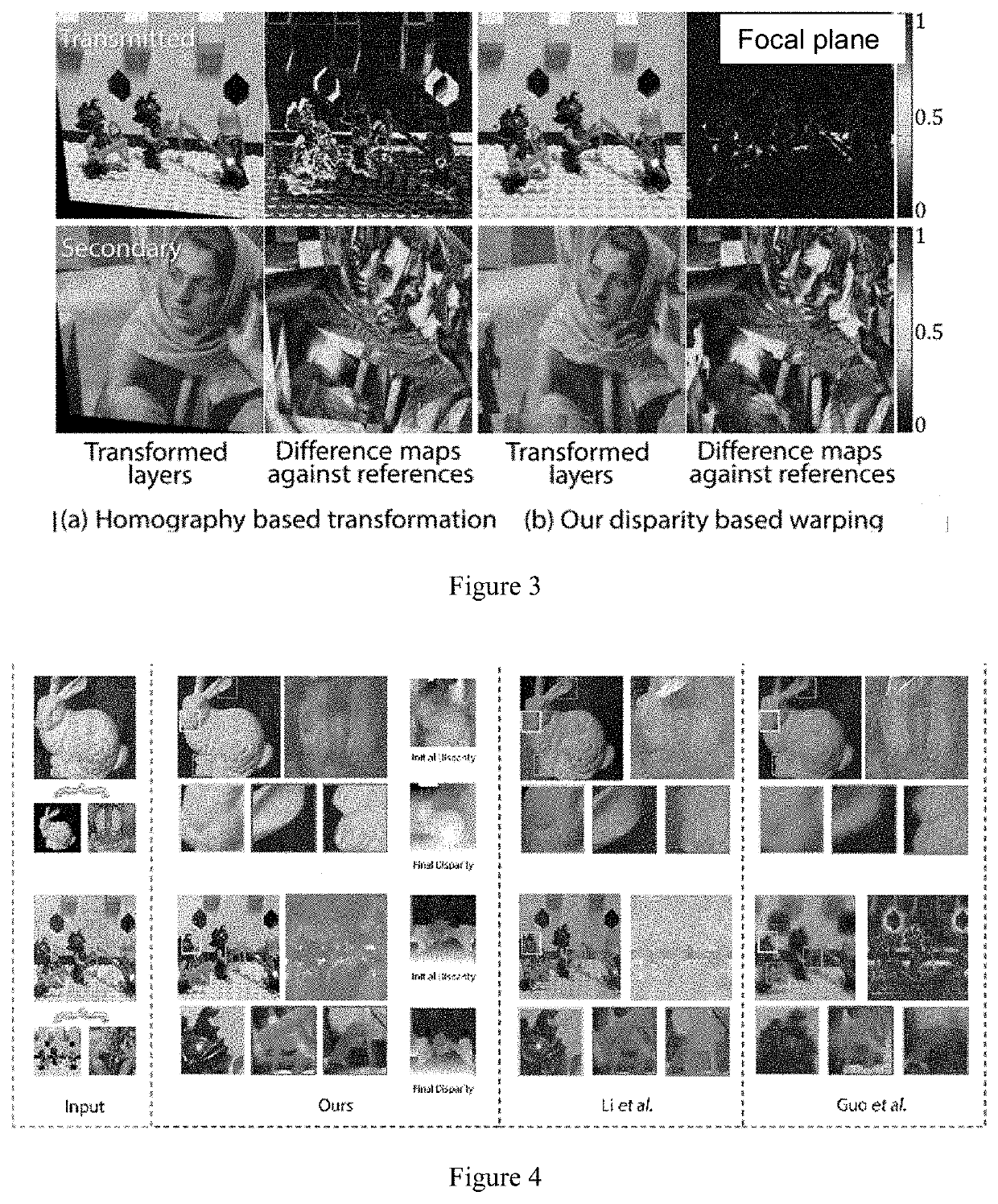
[0026]One approach to separate the layers for the reference view is by exploring redundant information that is available from the other views. To account for ...


PUM


Abstract

A method of processing light field images for separating a transmitted layer from a reflection layer. The method comprises capturing a plurality of views at a plurality of viewpoints with different polarization angles; obtaining an initial disparity estimation for a first view using SIFT-flow, and warping the first view to a reference view; optimizing an objective function comprising a transmitted layer and a secondary layer using an Augmented Lagrange Multiplier (ALM) with Alternating Direction Minimizing (ADM) strategy; updating the disparity estimation for the first view; repeating the steps of optimizing the objective function and updating the disparity estimation until the change in the objective function between two consecutive iterations is below a threshold; and separating the transmitted layer and the secondary layer using the disparity estimation for the first view.

Description

CROSS-REFERENCE TO RELATED APPLICATIONS[0001]This application is a continuation application of International Patent Application No. PCT / CN2019 / 083474, filed on Apr. 19, 2019, which is based on and claims the benefit of priority to International Application under Patent Cooperation Treaty, No. PCT / CN2018 / 083783, filed on Apr. 19, 2018. The above-referenced applications are incorporated herein by their entirety.TECHNICAL FIELD[0002]The present invention relates to image processing, and more particularly, to a method of light field based image processing.BACKGROUND[0003]A scene of interest is often placed behind a reflection or transparent layer. Typical examples include a picture behind a glass cover and a scene blocked by a sheer curtain. In such situations, the images can be generally modeled as a linear combination of the transmitted layer containing the scene of interest and the secondary layer containing the reflection or transparency. The images can be captured using light field...

Claims


Application Information

Patent Timeline
Patent Type & Authority Applications(United States)
IPC IPC(8): G06T5/50G06T7/557G06T7/593
CPCG06T5/50G06T7/557G06T2200/21G06T2207/10052G06T7/596G06T7/194G06T7/11
Inventor WU, MINYESHI, ZHIRUYU, JINGYI
Owner SHANGHAI TECH UNIV
Why Eureka
Try Eureka