Imaging lens
a technology of imaging lens and peripheral area, applied in the field of imaging lens, can solve the problems of inability to obtain excellent optical performance, difficult to correct aberrations at a peripheral area, etc., and achieve the effect of low profile, correcting aberrations properly, and high resolution
- Summary
- Abstract
- Description
- Claims
- Application Information
AI Technical Summary
Benefits of technology
Problems solved by technology
Method used
Image

Examples
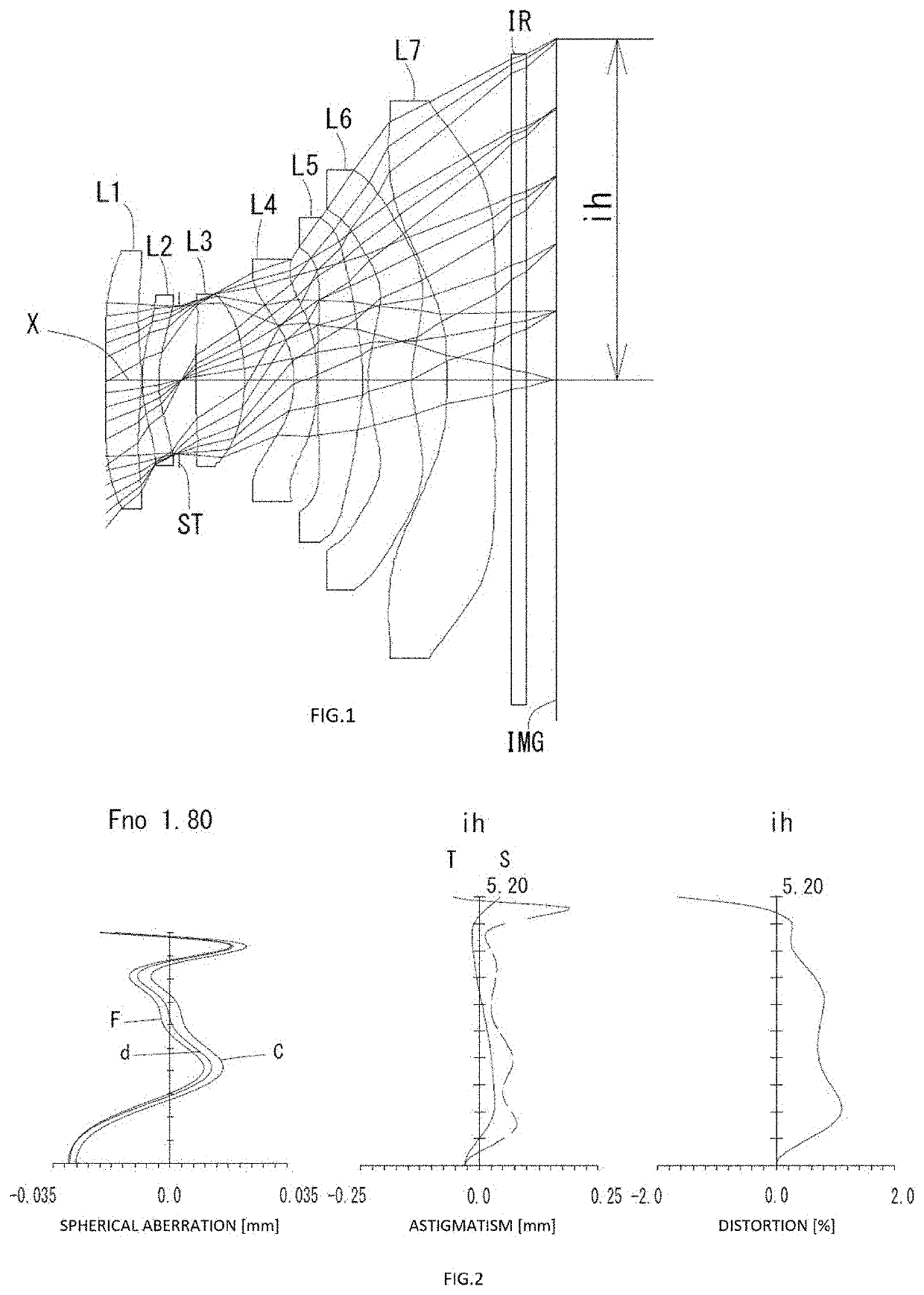
example 1
[0176]The basic lens data is shown below in Table 1.
TABLE 1Example 1Unit mmf = 4.40Fno = 1.80ω(°) = 50.0ih = 5.20TTL = 6.81Surface DatairdNdvd(Object)InfinityInfinity 1*−18.318330.53631.54456.44 (vd1) 2*−4.32960.0150 3*2.03270.25431.67119.24 (vd2) 4*1.67640.3186 5 (Stop)Infinity0.2399 6*8.14880.75301.53555.69 (vd3) 7*−3.02530.7547 8*−1.77320.35001.67119.24 (vd4) 9*−5.68050.0150 10*−11.48840.69161.54456.44 (vd5) 11*−2.61650.0779 12*1.85610.66831.67119.24 (vd6) 13*1.82560.5323 14*67.25940.70001.53555.69 (vd7) 15*4.35170.300018Infinity0.21001.51764.20 19Infinity0.4683mage InfinityPlanConstituent Lens DataLensStart SurfaceFocal Length1110.27523−19.987364.22448−3.9875106.05761221.241714−8.734Aspheric Surface DataFirst SurfaceSecond SurfaceThird SurfaceFourth SurfaceSixth SurfaceSeventh SurfaceEighth Surfacek0.000000E+000.000000E+000.000000E+000.000000E+000.000000E+009.000717E−010.000000E+00A44.352318E−021.400658E−01−1.016769E−01−2.459534E−01−1.012073E−02−1.484676E−02−2.450785E−0...
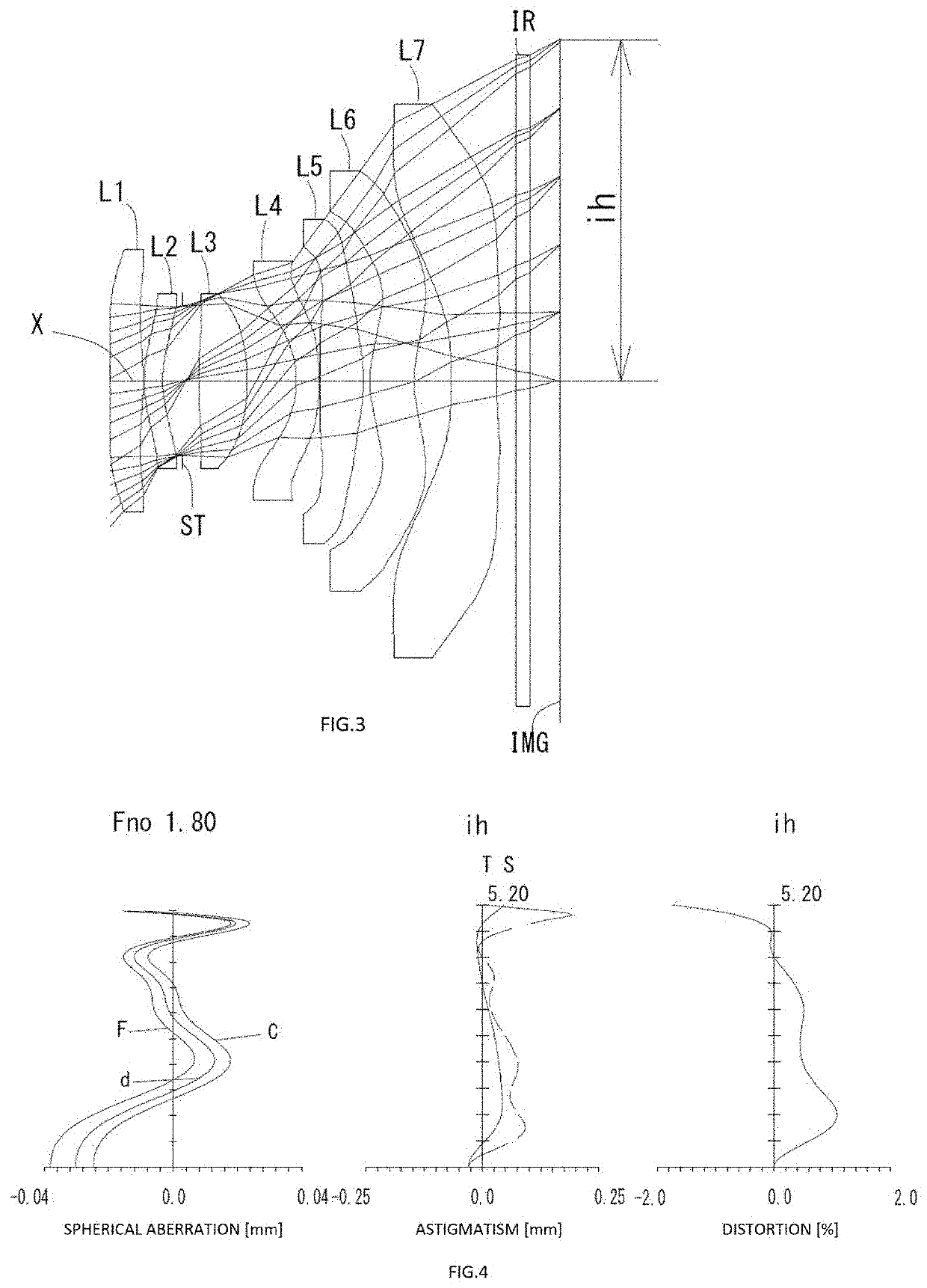
example 2
[0179]The basic lens data is shown below in Table 2.
TABLE 2Example 2Unit mmf = 4.41Fno = 1.80ω(°) = 50.0ih = 5.20TTL = 6.81Surface DatairdNdvd(Object)InfinityInfinity 1*−12.744770.50151.54456.44 (vd1) 2*−4.32460.0150 3*2.15930.28131.67119.24 (vd2) 4*1.81160.3074 5 (Stop)Infinity0.2442 6*7.47410.74121.53555.69 (vd3) 7*−3.22030.7507 8*−1.77950.35001.67119.24 (vd4) 9*−5.05870.0150 10*−9.79590.66221.54456.44 (vd5) 11*−2.71430.1024 12*1.79780.67431.67119.24 (vd6) 13*1.79580.5613 14*73.25030.70001.53555.69 (vd7) 15*4.32380.300018Infinity0.21001.51764.2019Infinity0.4656mage InfinityPlanConstituent Lens DataLensStart SurfaceFocal Length1111.77523−24.840364.31248−4.2765106.67661217.910714−8.622Aspheric Surface DataFirst SurfaceSecond SurfaceThird SurfaceFourth SurfaceSixth SurfaceSeventh SurfaceEighth Surfacek0.000000E+000.000000E+000.000000E+000.000000E+000.000000E+001.123803E+000.000000E+00A44.822204E−021.238152E−01−9.246960E−02−2.138569E−01−4.597134E−03−1.459368E−02−2.487210E−01A6−3.04...
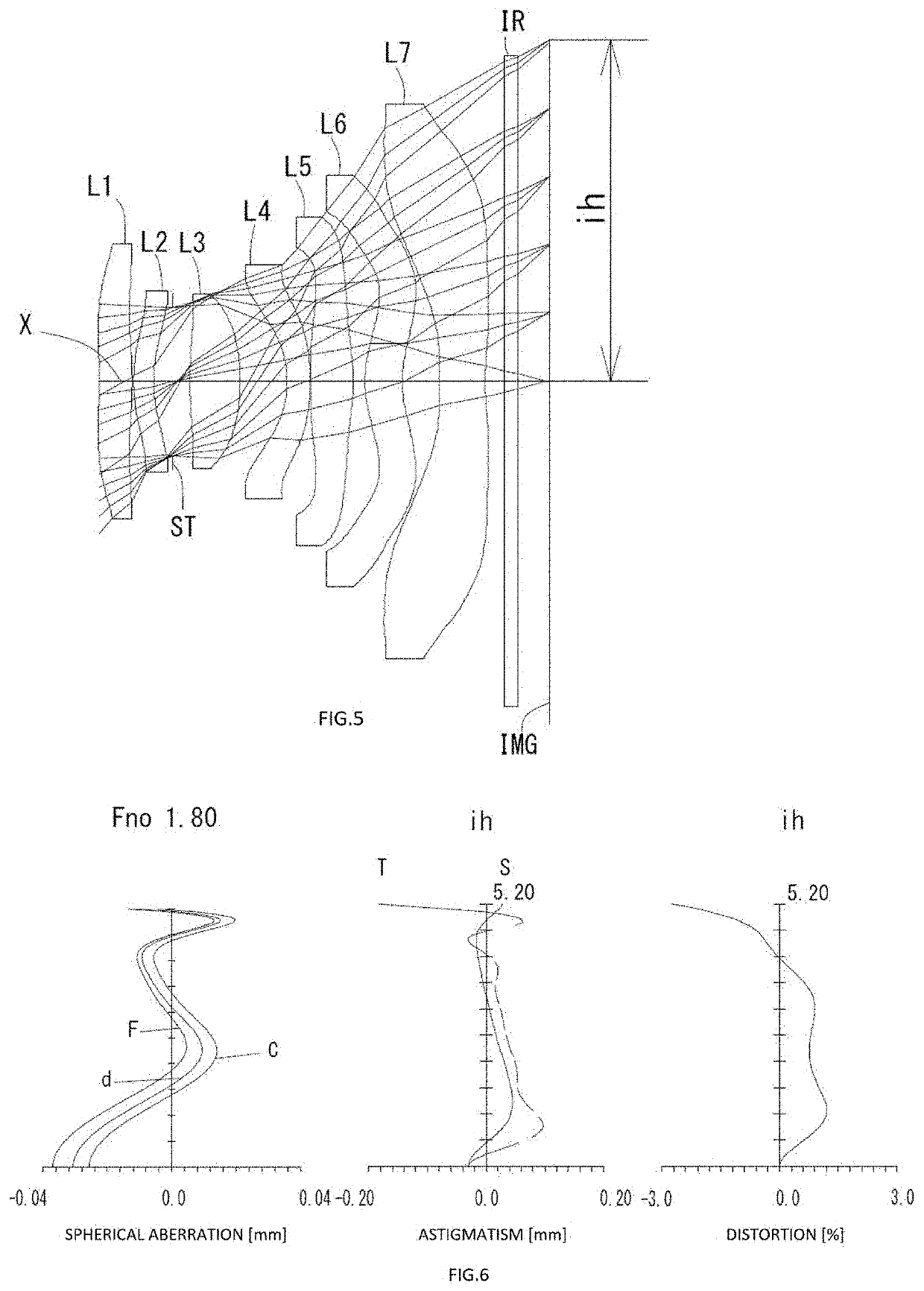
example 3
[0182]The basic lens data is shown below in Table 3.
TABLE 3Example 3Unit mmf = 4.40Fno = 1.80ω(°) = 50.3ih = 5.20TTL = 6.81Surface DatairdNdvd(Object)InfinityInfinity 1*−12.963250.50751.54456.44 (vd1) 2*−4.42570.0150 3*2.33970.30791.67119.24 (vd2) 4*1.92830.288 5 (Stop)Infinity0.2600 6*7.06150.76781.53555.69 (vd3) 7*−3.18960.7176 8*−1.79280.35011.67119.24 (vd4) 9*−4.81420.0150 10*−17.85540.64681.54456.44 (vd5) 11*−3.14300.1772 12*1.61630.56951.67119.24 (vd6) 13*1.58400.5707 14*60.4350.70001.53555.69 (vd7) 15*4.31890.300018Infinity0.21001.51764.2019Infinity0.4682mage InfinityPlanConstituent Lens DataLensStart SurfaceFocal Length1112.08923−23.380364.21848−4.4665106.89961219.436714−8.734Aspheric Surface DataFirst SurfaceSecond SurfaceThird SurfaceFourth SurfaceSixth SurfaceSeventh SurfaceEighth Surfacek0.000000E+000.000000E+000.000000E+000.000000E+000.000000E+001.160080E+000.000000E+00A44.524570E−021.232449E−01−6.563795E−02−1.788268E−01−6.306931E−03−1.940203E−02−2.447296E−01A6−2.4771...
PUM
 Abstract
Description
Claims
Application Information
 - R&D
- Intellectual Property
- Life Sciences
- Materials
- Tech Scout
- Unparalleled Data Quality
- Higher Quality Content
- 60% Fewer Hallucinations
Browse by: Latest US Patents, China's latest patents, Technical Efficacy Thesaurus, Application Domain, Technology Topic, Popular Technical Reports.
© 2025 PatSnap. All rights reserved.Legal|Privacy policy|Modern Slavery Act Transparency Statement|Sitemap|About US| Contact US: help@patsnap.com