System for controlling an air cushion vehicle by propeller towers and a propeller tower

a technology of air cushion and propeller tower, which is applied in the direction of air cushion, propulsive elements, vessel construction, etc., can solve the problems of air cushion vehicle wear, air bag and finger wear, air cushion skirt wear, etc., to prevent the wear of air bags and the cushion skirt, reduce the air, and avoid friction

Active Publication Date: 2021-04-08
HAKALA ASKO +1
View PDF0 Cites 0 Cited by
  • Summary
  • Abstract
  • Description
  • Claims
  • Application Information

AI Technical Summary

Benefits of technology

[0017]Wearing of the air bags and the skirt of the cushion is prevented by maintaining a constant amount of air in the cushion during a drive, so as to avoid friction due to reducing the air, which wears the cushion.
[0018]Varying wind conditions can be better handled by positioning propeller towers at the corners of the air cushion vehicle.

Problems solved by technology

More specifically, there is very little friction between the air cushion vehicle and ground, and the lack of friction makes the air cushion vehicle difficult to be maneuvered (compared to the car).
Another problem is to control the air cushion vehicle 100 in such a way that it will not collide straight with a large wave.
Increasing the friction facilitates turning the vessel 100 (in this case to the left), but the downside of friction is that the bags and fingers 304 of the cushion 104 wear down.
The first problem is wearing of the air bags and the skirt due to friction.
The second problem is controlling the air cushion vehicle under heavily varying wind conditions.
The third problem is imprecise control when the air cushion vehicle moves at slow speed.

Method used


Image

  • System for controlling an air cushion vehicle by propeller towers and a propeller tower
  • System for controlling an air cushion vehicle by propeller towers and a propeller tower
  • System for controlling an air cushion vehicle by propeller towers and a propeller tower

Examples


Embodiment Construction

[0033]It is to be noted that the embodiments presented in the description are given by way of example, and although a text describing an embodiment may include reference to another embodiment, such reference is generally only one alternative. Features relating to different embodiments may be combined in order to form new embodiments.

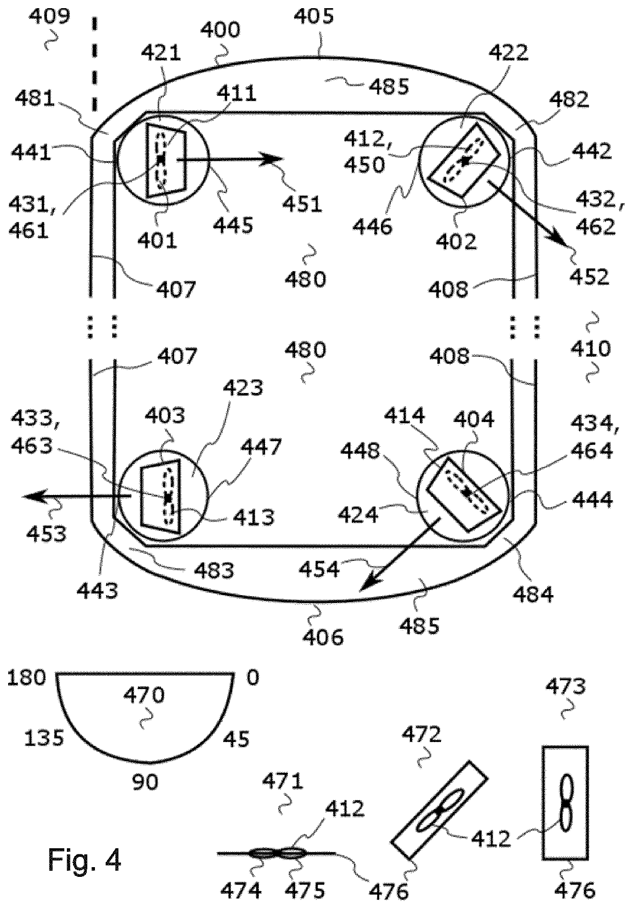
[0034]FIG. 4 is a bird's-eye view of a control system, abbreviated ‘system’, including four propeller towers 401-404 that are rotatable relative to an air cushion vehicle 400. The air cushion vehicle 400 may include a covered cockpit, but the cockpit may as well be uncovered. Thus, the centre part and the cockpit located between a bow 405 and a stern 406 of the air cushion vehicle 400 are not illustrated in the figure. The system is purposed for controlling the air cushion vehicle 400 by the rotatable propeller towers 401-404, wherein a first propeller tower 401 and a second propeller tower 402 are located in proximity to the bow 405 of the air cushion v...


PUM


Abstract

The invention relates to a control system for an air cushion vehicle (400) for the purpose of improving maneuverability of the air cushion vehicle. The system includes four propeller towers (401-404), propellers installed at the propeller towers, and mounting seats for mounting the propeller towers to the air cushion vehicle. In the system, an edge portion (442) located closest to a side wall N of the air cushion vehicle in the mounting seat is located closer to the ground than an opposite edge portion (446) in relation to a pivot point in the mounting seat, providing a tilt (450) of the propeller in response to rotation of the mounting seat at the pivot point, and in response to the rotation of the mounting seat, the propeller tower directs an air flow (452) produced with the propeller over the side wall of the air cushion vehicle and, due to the tilt of the propeller, partly downwardly relative to a horizontal plane defined by the ground, the air flow exerting a force (462) that lifts the side wall of the air cushion vehicle upwardly from the ground.

Description

[0001]Technical field: the invention generally relates to configuration of air-impelling propellers in an air cushion vehicle and directing the propellers.TECHNICAL BACKGROUND[0002]An air cushion vehicle is a vessel for moving on water, ice, bog or other places, over a relatively flat area. The cushion in the air cushion vehicle is formed by a number or air bags and a skirt enclosing the air bags. The air cushion vehicle is provided with an engine for driving air to the air bags so as to provide positive pressure in the air bags. Due to the positive pressure, the air cushion vehicle rises slightly upwards from its location, and hovers above an air mass, because the air mass released from the air bags remains for a short time between ground and the vehicle. Below the term ‘ground’ will be used, but there may be for example soil, vegetation, water or ice or their combination below the air cushion vehicle.[0003]The air cushion vehicle includes at least one airplane propeller or a corre...

Claims


Application Information

Patent Timeline
Patent Type & Authority Applications(United States)
IPC IPC(8): B60V1/14
CPCB60V1/14B60V1/04B60V1/11B60V1/16B63H7/02B60V1/043B63H7/00
Inventor HAKALA, ASKOHAKALA, PENTTI
Owner HAKALA ASKO
Why Eureka
Try Eureka