Ultrasonic sensor having a cover including a damping element

a technology of ultrasonic sensor and damping element, which is applied in the direction of acceleration measurement using interia force, generator/motor, instruments, etc., can solve the problems of difficult production implementation, adversely affecting the critical functional requirement of proximity measurement capability, and requiring exact parameters for gluing and foaming

Inactive Publication Date: 2011-12-20
ROBERT BOSCH GMBH
View PDF14 Cites 7 Cited by
  • Summary
  • Abstract
  • Description
  • Claims
  • Application Information

AI Technical Summary

Benefits of technology

[0029](V1) manufacturing of the cover and introduction of the second damping element into the opening of the cover;
[0029](V1) manufacturing of the cover and introduction of the second damping element into the opening of the cover;
[0031](V3) manufacture of the ultrasonic sensor by sealing the housing the cover.
[0032]It is preferred that while machining the partly equipped housing, the terminal leads are soldered onto the corresponding terminal points and the first damping element is inserted into the housing thereafter.
[0034]At its working frequency of 48 kHz, the ultrasonic sensor continues to have a low resistance and thus remains efficient. This is the result of the controlled damping of the diaphragm using insertion part 1. It may be actuated at lower transmission voltages and has higher generator voltages in the microphone range. The former is equivalent to a reduced risk of depolarization of the piezoceramic, reduced overmodulation of a transformer into non-linearity or the possibility of a smaller transformer transformation ratio and consequently the use of a smaller driver stage.
[0036]The cover itself may be prefabricated as an intermediate product including its introduced damping material independent of cycle times of the sensor production; buffering effects of a single-strand production line may be avoided. This damping material may be specifically designed for the wall oscillations.
[0038]The high transmission effect and improved signal-to-noise ratios for reception make the sensor well suited for implementing longer ranges for expanded functions such as parking space measurement, blind spot monitoring, LSF [Low-Speed Following], etc.
[0039]The proximity measurement capability of the sensor according to the present invention is improved in an unfoamed housing from approximately 28 cm . . . 30 cm to approximately 22 cm . . . 23 cm on the plausibilized binary signal.

Problems solved by technology

In particular, the chemical processes of gluing and foaming require exact parameters and are difficult to implement in production.
However, it is evident that as a result such sensors have less favorable attenuation characteristics than designs filled with foam, which adversely impacts the critical functional requirement for proximity measurement capability.
These are due to tilting and crumpling movements in the housing wall.
The second terminal lead is then soldered to the conductive housing (made of aluminum for example), being suitably connected to it by spot-drilling of the housing wall or attached to a housing stud, which is considered to be disadvantageous with respect to the number of components and the production expense.
A disadvantage in this connection is the non-homogeneous field / force distribution in the piezoceramic, since the upper surface, due to the D-cut, is only partially covered by the one (anode) contact (non-homogeneous plate capacitor).
Another disadvantage is that if the underside of the transducer element is improperly glued to the bottom of the housing (as a function of the thickness of the glue and roughness of the base), the underside of the transducer element is not in contact with frame ground (GND or ground) due to the peripheral contacting and the sensor is undesirably enabled to operate as a capacitor, making it sensitive to electrical interference fields.
In addition it is seen as disadvantageous that two contacts in the range of the useful oscillation are produced on the upper side of the transducer element as a result of the peripheral contacting.
Japanese Patent Application No. 2002238095 A describes an ultrasonic sensor having a cover, the housing being smooth-walled on the one hand and being designed with steps on the other, which require increased production expense.
The cover may be introduced into the housing offset in order to dampen specific oscillation modes, the setting of this position signifying increased expense.
The structure is complex and includes the construction of a pretensioned Teflon film.

Method used


Image

  • Ultrasonic sensor having a cover including a damping element
  • Ultrasonic sensor having a cover including a damping element
  • Ultrasonic sensor having a cover including a damping element

Examples


Embodiment Construction

[0047]Identical or similar components having identical or similar functions are provided with identical reference symbols in the figures.

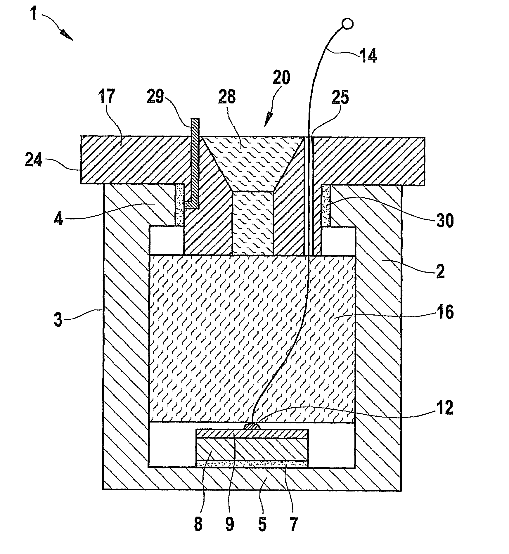
[0048]A sensor 1 according to the present invention is shown in FIG. 1 as an exemplary embodiment in a sectional representation. A housing 2 has a bottom 5 as a diaphragm.

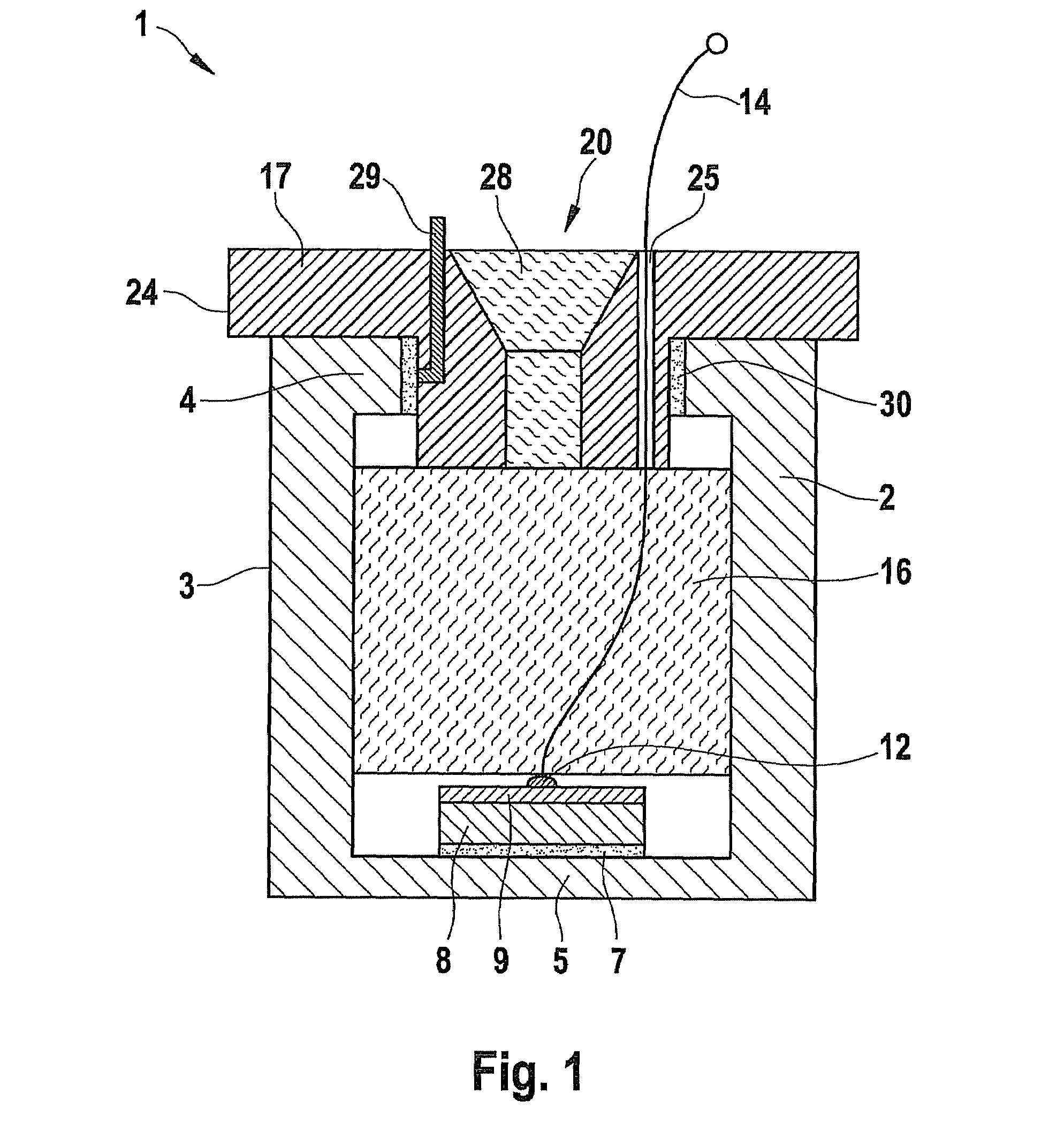
[0049]Furthermore, at its upper side, housing 2 has an edge 4 having an opening with a contour 6 (see FIG. 2), into which a cover 17 is inserted. Housing 2 is preferably an extruded aluminum part.

[0050]In the interior of housing 2, a transducer element 8 is fastened to the bottom of housing 2 by means of a connecting element 7, in this case a glue. only one side of transducer element 8 has a first plating 9 of a suitable metal, for example silver. Plating 9 is connected to a first lead 14 via a soldered joint in a first terminal point 12. Transducer elements 8 having a second coating 10 on their underside may also be used, connecting element 7 then being designed in the form of an...


PUM

PropertyMeasurementUnit
distanceaaaaaaaaaa
frequencyaaaaaaaaaa
frequencyaaaaaaaaaa

Abstract

An ultrasonic sensor, in particular for a vehicle, including a housing, includes the following: a transducer element which is attached to the bottom of the housing for generating ultrasonic oscillations; a first damping element situated in the housing for damping oscillations of the bottom; and a cover for sealing the housing, the cover being provided with a second damping element and having continuous tapering of the cover thickness in the region of the second damping element.

Description

FIELD OF THE INVENTION[0001]The present invention relates to an ultrasonic sensor for a vehicle and a corresponding method for manufacturing the same.BACKGROUND INFORMATION[0002]Ultrasonic sensors are used in motor vehicles, for example as parking assistance, a so-called proximity measurement capability in a distance range of less than 30 cm being a decisive functional requirement for that purpose. They are generally made up of a housing and a transducer element situated therein. The housing is customarily molded or milled from a metallic material, for example aluminum. For purposes of corrosion protection and enameling, it is coated with a primer. An electromechanical transducer element (e.g. a piezoelectric element) is attached to the bottom of the housing, for example, glued and contacted. The housing is filled with a damping material. An injected silicone foam is one possibility for this.[0003]For a number of reasons, these manufacturing steps are technically not trivial. In par...

Claims


Application Information

Patent Timeline
Patent Type & Authority Patents(United States)
IPC IPC(8): H01L41/08
CPCG10K9/122G10K11/002Y10T29/49007
Inventor REICHE, MARTIN
Owner ROBERT BOSCH GMBH
Why Eureka
Try Eureka