

Composite Cement Retainer
a cement retainer and composite cement technology, applied in the direction of sealing/packing, earthwork drilling and mining, borehole/well accessories, etc., can solve the problems of many retainers not performing as desired, taking too long to get into place, and taking too long to drill through
- Summary
- Abstract
- Description
- Claims
- Application Information
AI Technical Summary
Benefits of technology
Problems solved by technology
Method used
Image

Examples
Embodiment Construction
[0011]Several embodiments of Applicant's invention will now be described with reference to the drawings. Unless otherwise noted, like elements will be identified by identical numbers throughout all figures. The invention illustratively disclosed herein suitably may be practiced in the absence of any element which is not specifically disclosed herein.
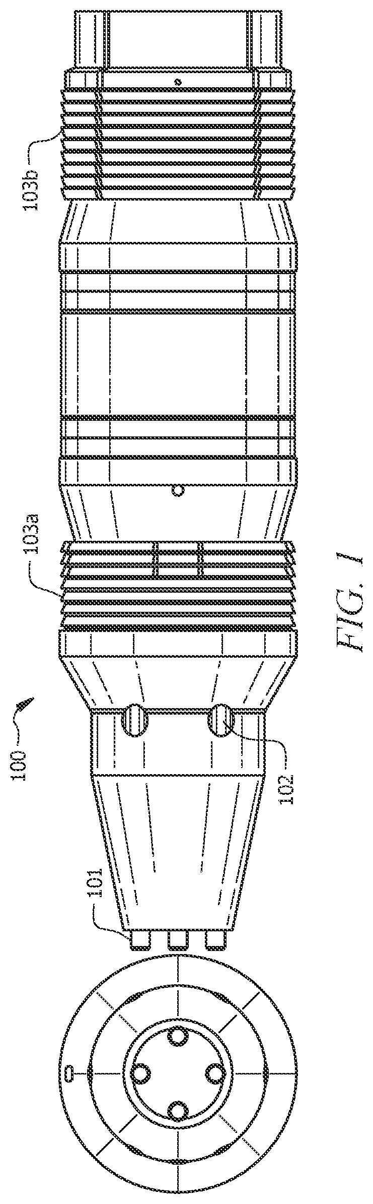
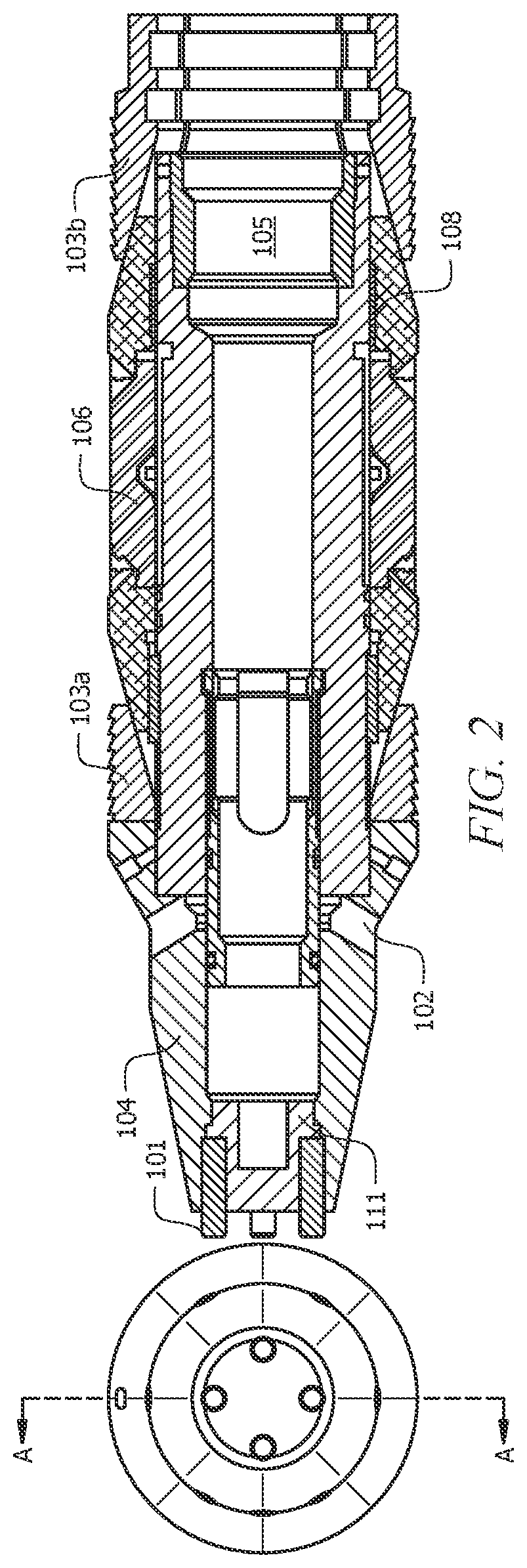
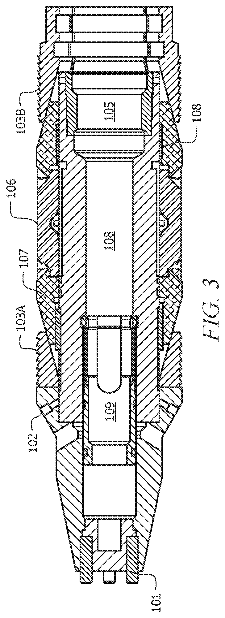
[0012]Cement retainers have wide and various uses throughout the oil and gas industry. They can be used to deliver cement downhole and squeeze and maintain the pressure downstream of the retainer. Cement retainers are very versatile. As noted, however, sometimes a cement retainer fails to stay in the correct location. If the retainer undesirably moves after placement, the retainer must often be retrieved and replaced. In such and other situations, it may become necessary to drill through the cement retainer to retrieve it from downhole. Cement retainers comprising mostly metal can take significant time and resources to drill through. The...
PUM
| Property | Measurement | Unit |
|---|---|---|
| effective diameter | aaaaa | aaaaa |
| diameter | aaaaa | aaaaa |
| pressure | aaaaa | aaaaa |
Abstract
Description
Claims
Application Information