Flow Diversion Valve for Downhole Tool Assembly

a technology of flow diversion valve and tool assembly, which is applied in the direction of tubing catchers, earth-moving drilling, and accessories in the wellbore/well. it can solve the problem of reducing the total strength of the connection holding the casing in the wellbor

Inactive Publication Date: 2021-04-22
STOKES DAVID A +3
View PDF0 Cites 3 Cited by
  • Summary
  • Abstract
  • Description
  • Claims
  • Application Information

AI Technical Summary

Benefits of technology

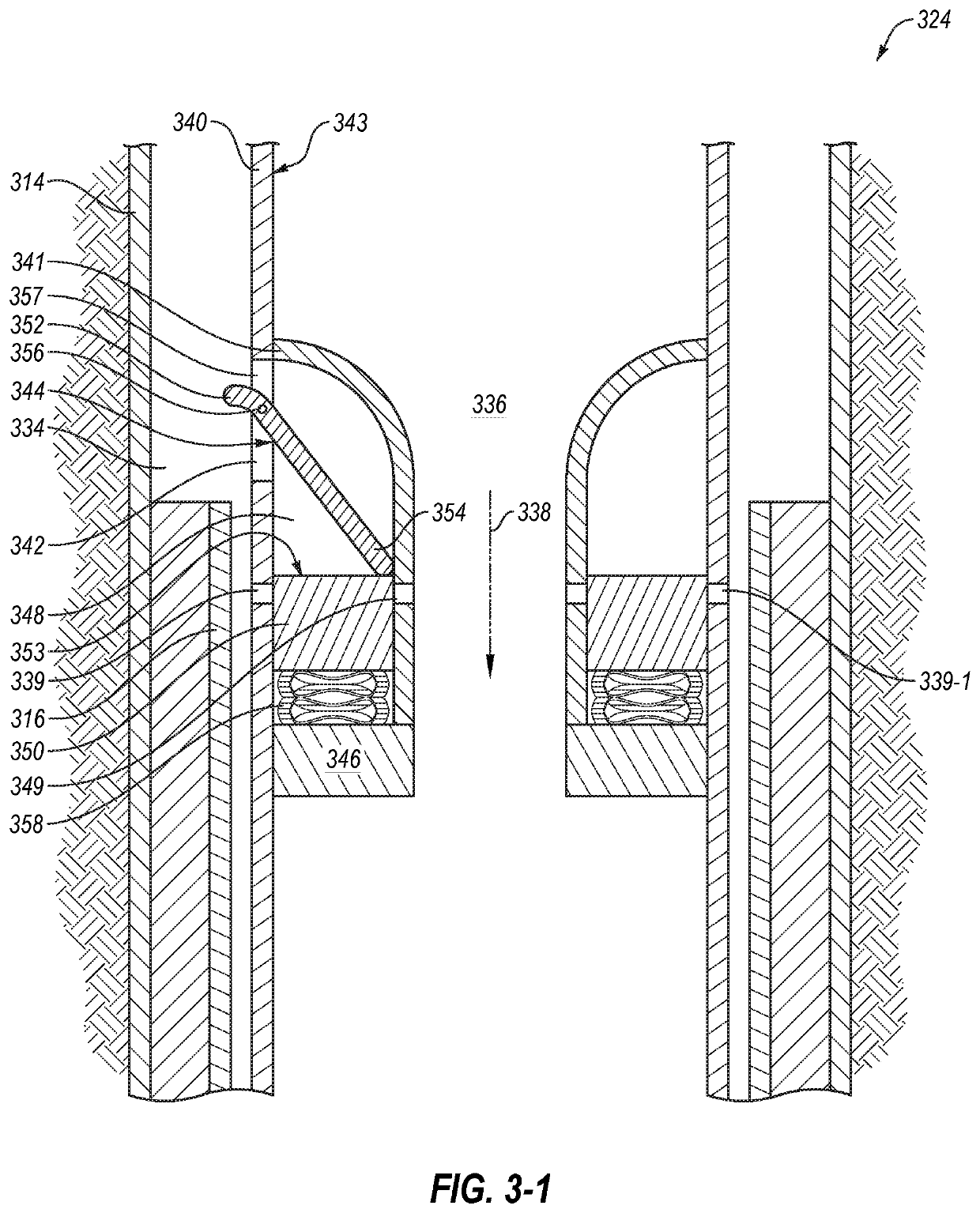
[0003]In one representative embodiment, a flow diversion valve is comprised of housing with upper and lower ends configured for coupling to another downhole tool to form a downhole tool assembly. The housing having defined through it a flow path and actuatable valve interposed in the flow path to control fluid flow from the lower end of the housing. The flow diversion valve has least one moveable actuation member that extends beyond the outer diameter of the housing under the influence of a biasing force and is configured to be the moved at least partially inwardly with respect to the housing against the biasing force when the flow diversion valve passes from a first casing to a second casing that has an inner diameter smaller than the inner diameter of the first casing. Movement of the actuating member changes the rate of fluid flow existing the flow diversion valve.

Problems solved by technology

If the removal force is insufficient to remove the casing, the casing may be cut to reduce the length of the casing to be removed, and therefore reduce the total strength of the connection holding the casing in the wellbore.

Method used


Image

  • Flow Diversion Valve for Downhole Tool Assembly
  • Flow Diversion Valve for Downhole Tool Assembly
  • Flow Diversion Valve for Downhole Tool Assembly

Examples


Embodiment Construction

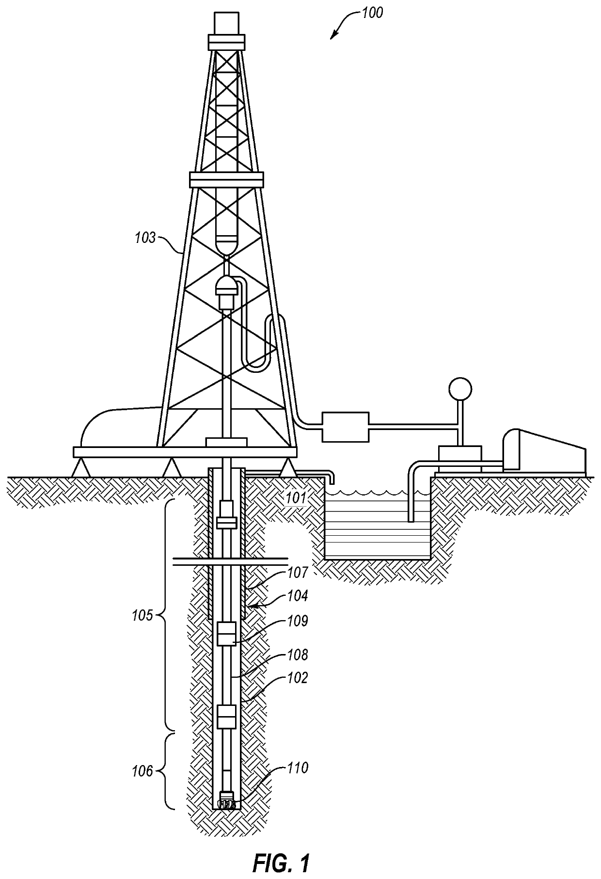
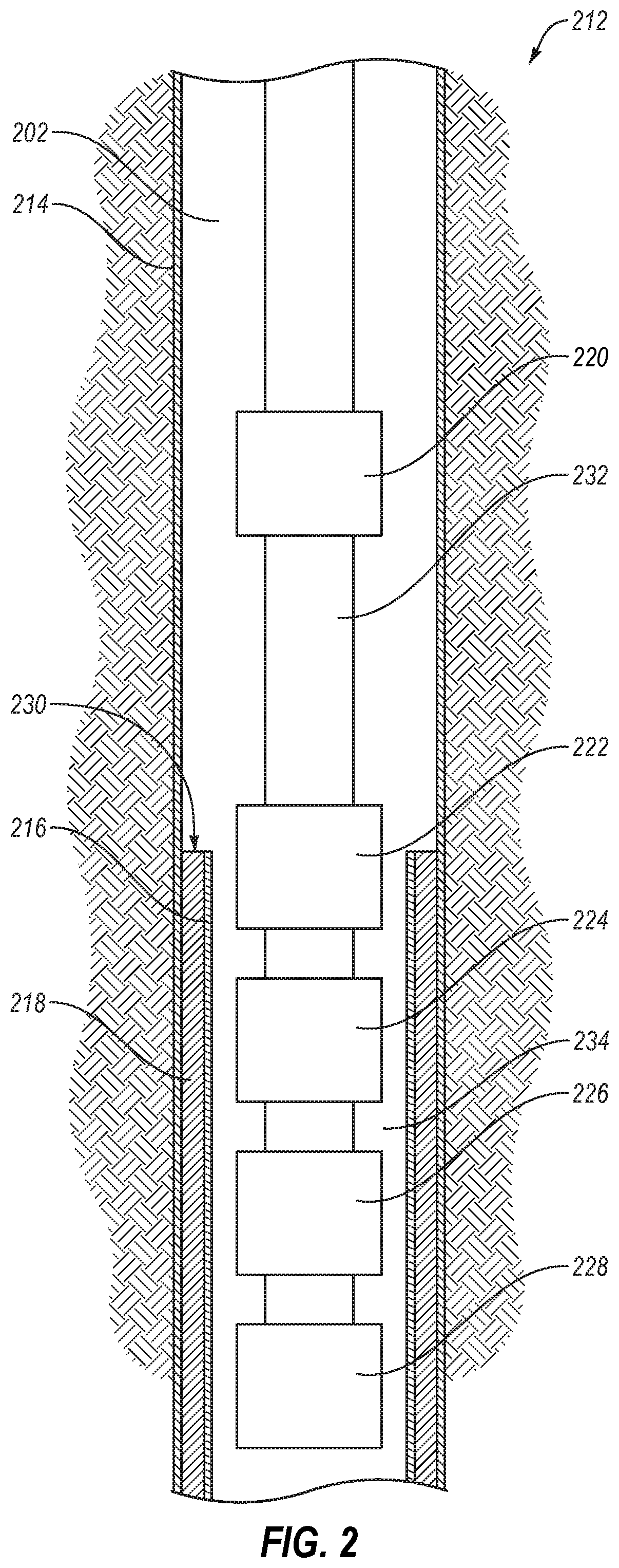
[0029]This disclosure generally relates to devices, systems, and methods for removing a casing from a wellbore. The system includes a flow diversion valve. When the flow diversion valve is closed, a fluid flow may drive a mud motor, which powers a casing cutter. To open the flow diversion valve, the flow diversion valve is lowered below a stump of an inner casing. When the flow diversion valve is open, at least a portion of the fluid flow may be diverted to the annulus between the flow diversion valve and the casing. The portion of the fluid flow diverted to the annulus is such that, downhole of the flow diversion valve, the fluid flow is insufficient to drive the mud motor. Thus, when the flow diversion valve is open, a hydraulically powered jack may pull on a spear connected to the casing without driving the mud motor. Therefore, by raising and lowering the flow diversion valve above and below the stump of the inner casing, the casing removal system may cycle between pulling on th...


PUM


Abstract

A casing removal system includes a flow diversion valve. The flow diversion valve includes a flow switch that engages an upper end of an inner casing. When the flow switch engages the upper end of the inner casing, the flow diversion valve opens and at least a portion of the fluid flow through the casing removal system exhausts to the annulus. The remaining fluid flow below the flow diversion valve is insufficient to operate a mud motor that drives a casing cutter. In other embodiments, when the flow switch is not engaged with the inner wall of casing, the flow diversion valve prevents fluid flow to components that are downhole of the valve and when the flow switch is engaged with the inner wall of casing, the flow diversion valve allows for fluid flow to components that are downhole of the valve.

Description

CROSS-REFERENCE TO RELATED APPLICATIONS[0001]This application claims the benefit of U.S. provisional patent application No. 62 / 891,451, filed Aug. 26, 2019, which is incorporated by reference for all purposes.BACKGROUND OF THE DISCLOSURE[0002]Well bores may be lined with one or more casings. Casings are installed to provide structure and geotechnical support for the wellbore, to facilitate fluid flow through the wellbore, and for many other reasons. Over the course of a wellbore's operational lifetime, and at the end of the wellbore's operational lifetime, it may be desirable to remove a casing. Casing removal involves gripping the casing with a spear and applying a removal force on the casing. If the removal force is insufficient to remove the casing, the casing may be cut to reduce the length of the casing to be removed, and therefore reduce the total strength of the connection holding the casing in the wellbore.SUMMARY[0003]In one representative embodiment, a flow diversion valve...

Claims


Application Information

Patent Timeline
Patent Type & Authority Applications(United States)
IPC IPC(8): E21B31/16E21B21/10E21B31/20
CPCE21B31/16E21B29/005E21B31/20E21B21/103E21B29/00E21B21/10E21B34/06E21B40/00
Inventor STOKES, DAVID A.PACKARD, GAVIN RAYBENNETT, ADAM M.CAMINARI, RICHARD
Owner STOKES DAVID A
Why Eureka
Try Eureka