
Visual Aid Timer System and Method of Using the Same

a technology of visual aids and timers, applied in the field of visual aid timer systems, can solve the problems of difficult advancement from one internal to the next, children with hearing impairments that struggle to learn information, and individuals with hearing impairments that are often at a disadvantage, and achieve the effect of higher scores

Active Publication Date: 2021-04-29
MARCUS MELISSA +1
View PDF10 Cites 0 Cited by
  • Summary
  • Abstract
  • Description
  • Claims
  • Application Information

AI Technical Summary

Benefits of technology

The present invention provides improved visual aid timer systems and methods for use in physical interval training and testing. These systems provide synchronized visual and auditory signals to users and represent the remaining time within each interval. Additionally, they may be utilized by individuals with hearing impairments and allow users to pace themselves and achieve higher scores. Overall, these systems enhance the training experience and make it more accessible to a wider range of individuals.

Problems solved by technology

In schools, children with hearing impairments struggle to learn information that is presented without specific accommodations for hearing impaired individuals.
Typically, the timed intervals become shorter over time, making the advancement from one internal to the next more and more difficult.
Individuals with hearing impairments are oftentimes at a disadvantage compared to others without hearing impairments.
Hearing impaired students often report that it is difficult to keep up with other students in interval training activities, as well as other standardized fitness training and testing, because they simply cannot hear audible cues to change or continue activities.
Moreover, even students that are not hearing impaired often have difficulty with interval training based on audible signals and cues.
This is so because while the audible cue may provide a “start” and a “stop” signal for an activity, it is difficult to glean how much time may be left within a particular interval.
Thus, for example, in PACER testing, when a student must move from one point to another over the timed interval, the student does not typically know how long the interval may be.
Even when intervals are consistent, it can be difficult to glean an amount of time left in an interval for the user to move from the one point to the other.

Method used


Image

  • Visual Aid Timer System and Method of Using the Same
  • Visual Aid Timer System and Method of Using the Same
  • Visual Aid Timer System and Method of Using the Same

Examples


Embodiment Construction

[0043]The present invention relates to a visual aid timer system. Specifically, the visual aid timer system comprises a visual aid timer that may be displayed to users, and synchronized to an audible alert signal providing expirations of time intervals and / or indications of start and / or stop times in a plurality of intervals used in physical fitness training and / or testing. The visual aid timer system provides a visual indication of time remaining in each of the plurality of intervals for viewing by users thereof. Methods of using the same are further provided.

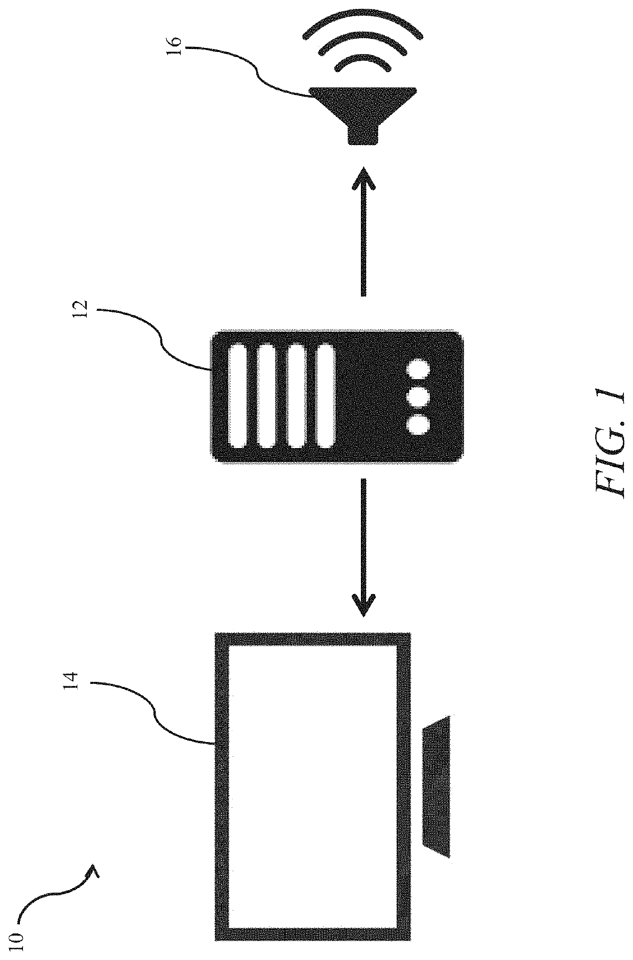
[0044]Now referring to the figures, wherein like numerals refer to like parts, FIG. 1 illustrates a system 10 for providing both audible and visual signals for users during fitness interval testing, such as through the PACER test. Specifically, the system 10 may comprise a control 12, such as, for example, a video and audio player 12, such as a DVD player, a computer showing video / audio files and / or having streaming capabiliti...


PUM


Abstract

Visual aid timer systems comprise a visual aid timer that may be displayed to users, and synchronized to an audible alert signal providing expirations of time intervals and / or indications of start and / or stop times in a plurality of intervals used in physical fitness training and / or testing. The visual aid timer system provides a visual indication of time remaining in each of the plurality of intervals for viewing by users thereof. Methods of using the same are further provided.

Description

CROSS-REFERENCE TO RELATED APPLICATIONS[0001]The present invention claims priority to U.S. Prov. Pat. App. No. 62 / 925,637, titled “Customizable Visual Aid Timer,” filed Oct. 24, 2019, which is incorporated herein by reference in its entirety.TECHNICAL FIELD[0002]The present invention relates to a visual aid timer system. Specifically, the visual aid timer system comprises a visual aid timer that may be displayed to users, and synchronized to an audible alert signal providing expirations of time intervals and / or indications of start and / or stop times in a plurality of intervals used in physical fitness training and / or testing. The visual aid timer system provides a visual indication of time remaining in each of the plurality of intervals for viewing by users thereof. Methods of using the same are further provided.BACKGROUND[0003]More than two-thirds of people categorize themselves as “visual” or “spatial” learners. This means that they understand information effectively when content ...

Claims


Application Information

Patent Timeline
IPC IPC(8): A63B71/06G03B21/12G06M3/06G06T13/80
CPCA63B71/0622G03B21/12A63B2071/0641G06T13/80A63B2071/0625G06M3/06G03B21/00G07C1/22
Inventor MARCUS, MELISSAMARCUS, JR., DONALD
Owner MARCUS MELISSA
Learn More