
Modular Electrical Distribution System for Vehicles

a technology of modular electrical distribution system and vehicle, which is applied in the direction of electrical/fluid circuit, electrical apparatus casing/cabinet/drawer details, casing/cabinet/drawer details, etc., can solve the problems of complicated power disconnecting from the rv electrical system, long runs of heavy gauge electrical wires,

Active Publication Date: 2021-05-06
STEINER ENTERPRISES
View PDF3 Cites 1 Cited by
  • Summary
  • Abstract
  • Description
  • Claims
  • Application Information

AI Technical Summary

Benefits of technology

The patent is about a modular electrical distribution system for RVs that allows for the safe and efficient distribution of electricity. The system includes a housing with water-tight openings for receiving electrical cables or wires from the vehicle and other electrical devices. The system also includes a power-in assembly, a trailer connection assembly, and a breaker assembly that can be customized for the specific needs of the RV. The breaker assembly includes a disconnect switch for easy maintenance and a separate circuit for connection to an auxiliary power source. The technical effects of the patent text include improved safety, efficiency, and flexibility in the distribution of electrical power for RVs.

Problems solved by technology

As a consequence, electrical signal and power distribution systems for RVs have become increasingly complex.
The wiring harnesses are frequently a jumbled array of wires, electrical connectors and fuses that are beyond the technical ability of many RVers to use.
Disconnecting power from the RV electrical system can be complicated by the location of the disconnect switch, which is usually separate from the distribution harness.
This leads to the need for long runs of heavy gauge electrical wire, not to mention the inconvenience of locating the switch, especially for the larger RVs.

Method used


Image

  • Modular Electrical Distribution System for Vehicles
  • Modular Electrical Distribution System for Vehicles
  • Modular Electrical Distribution System for Vehicles

Examples


Embodiment Construction

[0023]For the purposes of promoting an understanding of the principles of the disclosure, reference will now be made to the embodiments illustrated in the drawings and described in the following written specification. It is understood that no limitation to the scope of the disclosure is thereby intended. It is further understood that the present disclosure includes any alterations and modifications to the illustrated embodiments and includes further applications of the principles disclosed herein as would normally occur to one skilled in the art to which this disclosure pertains

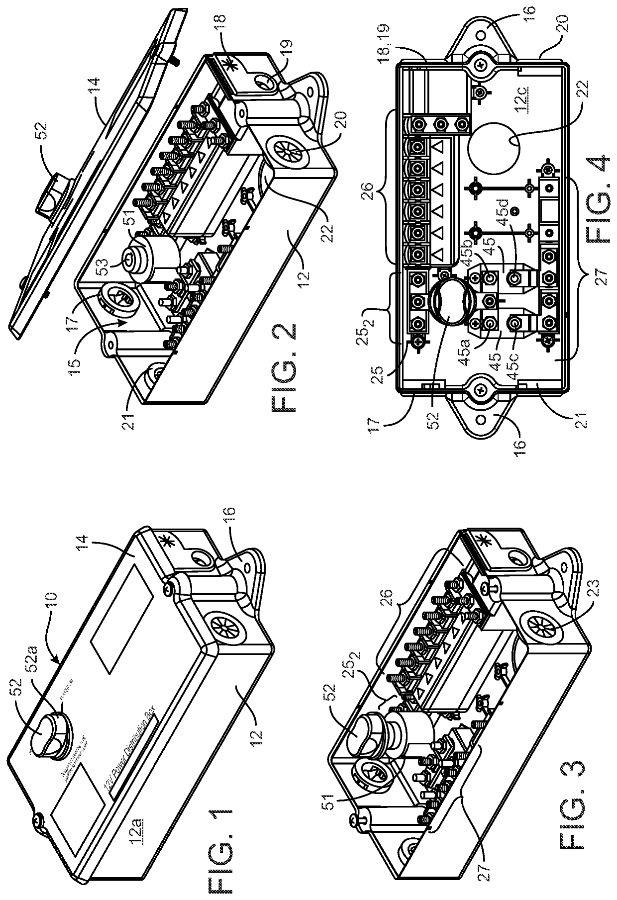
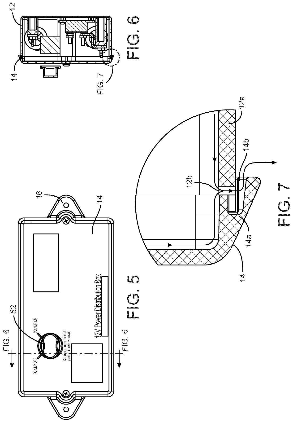
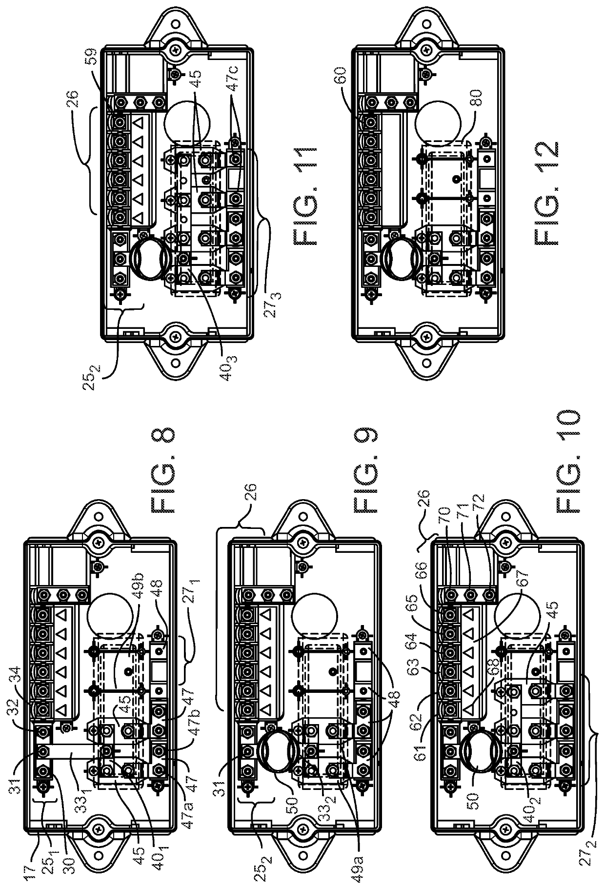
[0024]A configurable modular electrical distribution system 10 for a recreational vehicle includes a weatherproof housing 12 and a weatherproof cover 14 defining an enclosure 15 for containing electrical components, as shown in FIGS. 1-13. The cover 14 can be provided with a seal ring 14d or similar structure to form a water-tight seal with the housing. The housing 12 includes a mounting feature, such as moun...


PUM


Abstract

A modular electrical distribution system for an RV comprises a water-tight housing for mounting to the RV with a plurality of water-tight openings for receiving electrical cables or wires from a towing vehicle and / or auxiliary electrical devices. The system includes a power-in assembly, a trailer connection assembly and a breaker assembly that can be tailored to the particular electrical distribution needs of the RV. The trailer connection assembly includes a plurality of electrical terminals for engagement to wires connected to electrical components of the towing vehicle, such as brake lights, turn signal lights, etc. The breaker assembly includes a plurality of circuit breakers or fuses connected to the power-in assembly and to a plurality of corresponding output bars with output terminals to connect to the cables / wires for the auxiliary electrical devices. The system can include an auxiliary circuit for connection to an auxiliary power source, such as a solar panel array.

Description

REFERENCE TO RELATED APPLICATION AND PRIORITY CLAIM[0001]This application is a utility filing from and claims priority to U.S. Provisional Application No. 62 / 931,249, filed on Nov. 6, 2019, the entire disclosure of which is incorporated herein by reference.BACKGROUND[0002]Recreational vehicles (RV) have evolved to incorporate many electrical components that can be powered by the RV electrical power system (i.e., the RV battery), as well as the ability to tow adjunct vehicles with parallel lighting arrangements that are also powered by the RV electrical power system. As a consequence, electrical signal and power distribution systems for RVs have become increasingly complex. At present wiring harnesses are used to connect the RV to the various electrical components and to connect the RV to the lighting arrangement of the towed vehicle. The wiring harnesses are frequently a jumbled array of wires, electrical connectors and fuses that are beyond the technical ability of many RVers to us...

Claims


Application Information

Patent Timeline
Patent Type & Authority Applications(United States)
IPC IPC(8): H05K5/02H02G5/06B60R16/023
CPCH05K5/0247B60R16/0238H02G5/06
Inventor HICKS, THOMAS P.DEWITT, DONALD E.DEWITT, JOSHUA E.BROCK, JONATHANGIGGY, BRAD
Owner STEINER ENTERPRISES
Learn More