
Magnetized water generating device

Active Publication Date: 2021-05-13
KIM KEUN SOON
View PDF0 Cites 0 Cited by
  • Summary
  • Abstract
  • Description
  • Claims
  • Application Information

AI Technical Summary

Benefits of technology

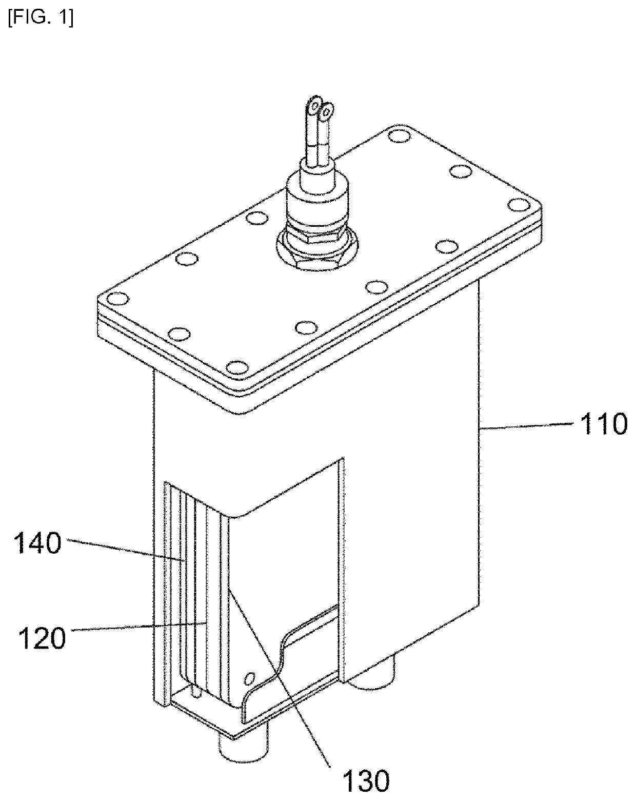
[0032]According to the present invention, by arranging the plurality of heating plates 130, 140, which are induction conductors, around the induction coil 120 at a predetermined interval from the induction coil 120 installed at the center inside the tube body 110, whose interior is filled with water, and applying high-frequency power to the induction coil 120 causing the induction coil 120 to induce this high-frequency power to the plurality of heating plates 130, 140, the plurality of heating plates 130, 140 are heated, so that the water filling the interior of the tube body 110 is heated and converted into micro-cluster magnetized water, and then the micro-cluster magnetiz

Problems solved by technology

However, the magnetization degree of the thus magnetized water is low.
However, in such magnetized water generating process, it is difficult to know magne

Method used


Image

  • Magnetized water generating device
  • Magnetized water generating device
  • Magnetized water generating device

Examples


Example

BEST MODE

[0038]Hereinafter, embodiments of the present invention will be described in detail with reference to accompanying drawings.

[0039]FIG. 1 is a diagram showing an embodiment of a tube body110 constituting a magnetized water generating device according to the present invention, wherein an induction coil 120 and a plurality of heating plates 130 and 140 are configured inside the tube body 110.

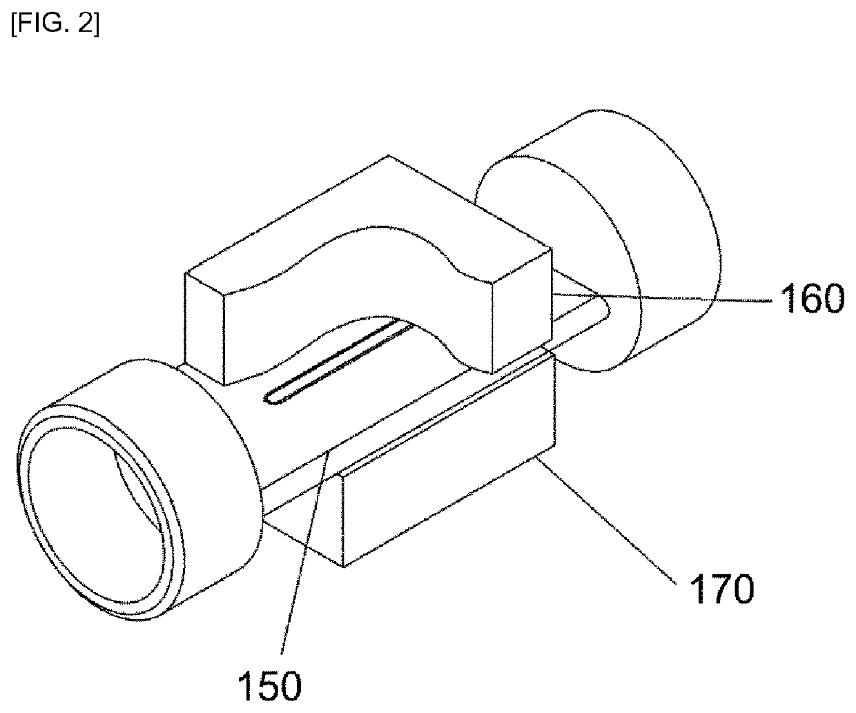
[0040]FIG. 2 is a diagram showing an embodiment of a tube 150 and a pair of magnets 160, 170 constituting the magnetized water generating device according to the present invention.

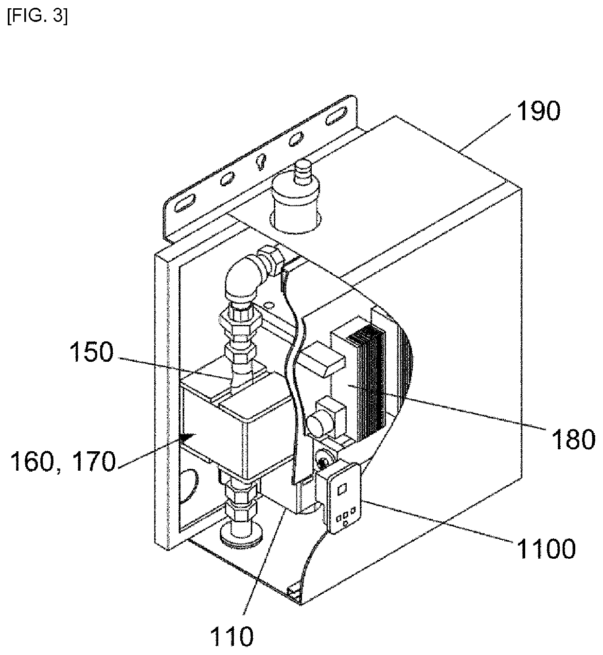
[0041]FIG. 3 is a diagram showing an embodiment of the magnetized water generating device according to the present invention shown by combining FIGS. 1 and 2. The magnetized water generating device includes the tube body 110, the tube 150, the pair of magnets 160, 170 and a high frequency generator 180, all of which are configured inside an outer casing 190. In this configuration, an on-off switch 1100 is install...


PUM


Abstract

A magnetized water generating device includes a tube body 110 being filled with water; an induction coil 120 installed at a center inside the tube body 110; and a plurality of heating plates 130, 140 arranged around the induction coil 120. The magnetized water generating device further includes a high frequency generator 180 for applying high-frequency power to the induction coil 120 to heat the plurality of heating plates 130, 140, resulting in that the water in the tube body 110 is heated and converted into micro-cluster magnetized water; and a tube 150, positioned between a pair of magnets 160, 170 for causing the micro-cluster magnetized water to pass through an N-pole and an S-pole resulting from the pair of magnets 160, 170, thereby providing it as magnetized water exhibiting a high degree of electric conductivity.

Description

TECHNICAL FIELD[0001]The present invention relates to a magnetized water generating device.BACKGROUND ART[0002]Generally, it is common knowledge that the water exhibits magnetism or changes its electrical conductivity characteristics at a moment of passing through a magnetic field of the magnets, by allowing water to flow between or around installed magnets, after permanent magnets or electromagnets are installed at corresponding position, so that water is allowed to be generated as magnetized water.[0003]However, the magnetization degree of the thus magnetized water is low.[0004]Information on related prior art document: Registered Patent Publication No. 10-1434193 published on Aug. 28, 2014 titled “Super-high-efficiency induction hot water heater.”[0005]Further, in general, water, which is subjected to magnetization treatment, is magnetized to generate magnetized water.[0006]However, in such magnetized water generating process, it is difficult to know magnetization ratio of water,...

Claims


Application Information

Patent Timeline
IPC IPC(8): C02F1/48C02F1/00H01F5/00G05D7/06
CPCC02F1/487C02F1/482C02F1/485C02F1/008H01F5/00G05D7/0652C02F2101/12C02F2201/483C02F2209/06C02F2209/05C02F2209/29C02F2209/40C02F2209/02C02F2201/005C02F1/48C02F1/02C02F1/005H05B6/108
Inventor KIM, KEUN SOON
Owner KIM KEUN SOON
Learn More