Control apparatus for camshaft phaser
a control apparatus and camshaft technology, applied in the direction of valve operating means/release devices, functional valve types, machines/engines, etc., can solve the problems of difficult to achieve, inability to use the control device, and the central oil supply of the phaser
- Summary
- Abstract
- Description
- Claims
- Application Information
AI Technical Summary
Benefits of technology
Problems solved by technology
Method used
Image
Examples
first embodiment
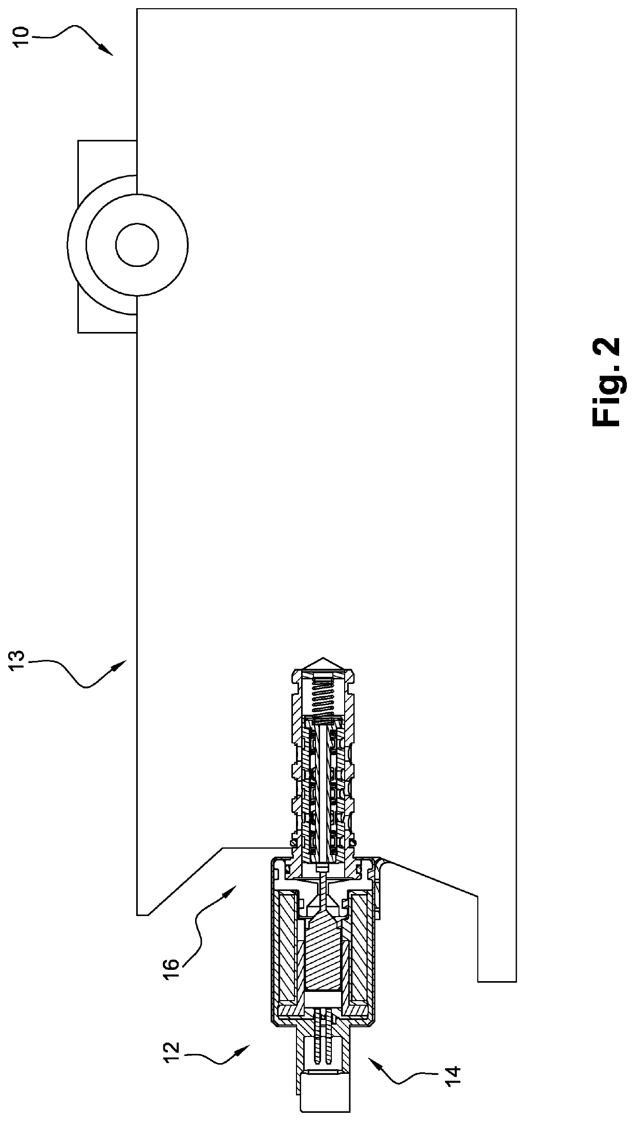
[0042]A first embodiment is described according to FIG. 5. The valve assembly 34 is tubular, i.e. it has a cylindrical shape and is open at both ends 66. Oil can flow through the internal volume of the valve assembly 34, with the oil flowing in the direction of the central longitudinal axis X. The thickness of the tube of the valve assembly 34 is very small compared to its diameter, i.e. of the order of 0.1% to 10%. The valve assembly 34 includes at least three rigid rings 68 and at least a first valve 70, a second valve 71 and a third valve 73. Each valve 70, 71, 73 comprises at least one vane 62 connected to two flexible arms 72, 74 and each valve 70, 71, 73 is connected to two consecutive rigid rings 68. The valve assembly 34 includes at least one angular indexing element 76 formed by an internal or external notch. As shown in FIGS. 2, 3 and 4, the angular indexing element 76 does not allow rotation of the valve assembly 34 inside the body 28 of the hydraulic element 16. The rigi...
second embodiment
[0046]In a second embodiment, the control valve assembly 34 depicted in FIG. 6 is tubular, i.e. has a cylindrical shape and is open at both ends 80. The shape of the control valve assembly 34 is referred to as an origami shape. The valve assembly 34 includes at least three valves 70. Each valve 70 comprises at least one vane 62 connected to a flexible arm 82 and a rigid element 86. The valve assembly 34 further includes a longitudinal bar 84 extending along the central longitudinal axis X. The longitudinal bar 84 connects two contiguous valves 70, 71, 73. Two contiguous valves 70 are interconnected by a longitudinal bar 84 extending along the axis X. The arm 82 is arranged longitudinally along the axis X. The longitudinal bar 84 is arranged between the two contiguous rigid elements 86. The longitudinal bar 84 serves as an index for the valve assembly 34. The vane 62 is elongate in the tangential direction of the tubular valve assembly 34. The shape of the vane 62 defines a rectangul...
PUM
 Abstract
Description
Claims
Application Information
 - R&D
- Intellectual Property
- Life Sciences
- Materials
- Tech Scout
- Unparalleled Data Quality
- Higher Quality Content
- 60% Fewer Hallucinations
Browse by: Latest US Patents, China's latest patents, Technical Efficacy Thesaurus, Application Domain, Technology Topic, Popular Technical Reports.
© 2025 PatSnap. All rights reserved.Legal|Privacy policy|Modern Slavery Act Transparency Statement|Sitemap|About US| Contact US: help@patsnap.com


